
How to Use LCD Display 128x64 (ST7920): Examples, Pinouts, and Specs
 Design with LCD Display 128x64 (ST7920) in Cirkit Designer
Introduction
The LCD Display 128x64 (ST7920) is a graphical LCD module with a resolution of 128x64 pixels. It is widely used in embedded systems for displaying text, graphics, and images. The display is powered by the ST7920 controller, which supports both parallel and serial (SPI) communication, making it versatile and easy to integrate into various microcontroller-based projects.
Explore Projects Built with LCD Display 128x64 (ST7920)
 Open Project in Cirkit Designer
 Open Project in Cirkit Designer
 Open Project in Cirkit Designer
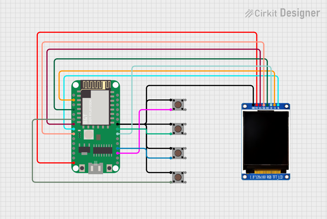 Open Project in Cirkit Designer
Explore Projects Built with LCD Display 128x64 (ST7920)
Open Project in Cirkit DesignerOpen Project in Cirkit DesignerOpen Project in Cirkit DesignerOpen Project in Cirkit DesignerCommon Applications
- Embedded systems and microcontroller projects
- Industrial control panels
- DIY electronics and hobbyist projects
- Data loggers and monitoring systems
- User interfaces for appliances and devices
Technical Specifications
Below are the key technical details of the LCD Display 128x64 (ST7920):
| Parameter | Specification |
|---|---|
| Display Resolution | 128x64 pixels |
| Controller | ST7920 |
| Communication Modes | Parallel (8-bit/4-bit) or Serial (SPI) |
| Operating Voltage | 4.5V to 5.5V |
| Operating Current | ~1.2mA (backlight off) |
| Backlight Voltage | 4.2V to 4.6V |
| Backlight Current | ~120mA |
| Operating Temperature | -20°C to 70°C |
| Dimensions | ~93mm x 70mm x 12mm |
Pin Configuration
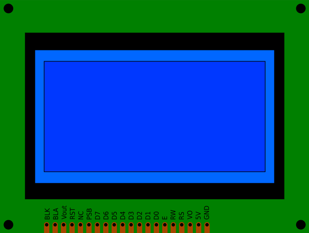
The LCD Display 128x64 (ST7920) has a 20-pin interface. The pin configuration is as follows:
| Pin | Name | Description |
|---|---|---|
| 1 | VSS | Ground (0V) |
| 2 | VDD | Power supply (4.5V to 5.5V) |
| 3 | VO | Contrast adjustment (connect to a potentiometer) |
| 4 | RS | Register Select (0: Command, 1: Data) |
| 5 | RW | Read/Write (0: Write, 1: Read) |
| 6 | E | Enable signal (used to latch data) |
| 7-14 | DB0-DB7 | Data bus lines (used in parallel mode) |
| 15 | PSB | Interface selection (0: Serial, 1: Parallel) |
| 16 | NC | Not connected |
| 17 | RST | Reset pin (active low) |
| 18 | VOUT | Voltage output for internal use (connect a capacitor for stability) |
| 19 | BLA | Backlight anode (+) |
| 20 | BLK | Backlight cathode (-) |
Usage Instructions
Connecting the LCD to a Microcontroller
The LCD Display 128x64 can be used in either parallel or serial mode. Below are the steps for connecting it to an Arduino UNO in serial mode (SPI), which requires fewer pins.
Wiring Diagram (Serial Mode)
| LCD Pin | Arduino Pin |
|---|---|
| VSS | GND |
| VDD | 5V |
| VO | Potentiometer (middle pin) |
| RS | D8 |
| RW | GND |
| E | D9 |
| PSB | GND |
| RST | D10 |
| BLA | 5V |
| BLK | GND |
Arduino Code Example
Below is an example of how to use the LCD Display 128x64 in serial mode with an Arduino UNO. This code uses the U8g2 library, which supports the ST7920 controller.
#include <U8g2lib.h>

// Initialize the display in SPI mode. Adjust the pins as per your wiring.
U8G2_ST7920_128X64_F_SW_SPI u8g2(U8G2_R0, /* clock=*/ 9, /* data=*/ 8, /* cs=*/ 10);

// Setup function
void setup() {
  u8g2.begin(); // Initialize the display
  u8g2.setFont(u8g2_font_ncenB08_tr); // Set font for text
}

// Loop function
void loop() {
  u8g2.clearBuffer(); // Clear the display buffer
  u8g2.drawStr(0, 10, "Hello, World!"); // Draw text at (0, 10)
  u8g2.drawBox(10, 20, 50, 30); // Draw a filled rectangle
  u8g2.sendBuffer(); // Send the buffer to the display
  delay(1000); // Wait for 1 second
}
Important Considerations
- Contrast Adjustment: Use a 10kΩ potentiometer connected to the VO pin to adjust the display contrast.
- Backlight Power: Ensure the backlight pins (BLA and BLK) are connected to a suitable power source (typically 5V).
- Communication Mode: Set the PSB pin to GND for serial mode or VDD for parallel mode.
- Capacitor on VOUT: Connect a 1µF capacitor between VOUT and GND for stable operation.
Troubleshooting and FAQs
Common Issues
Blank Screen:
- Check the power supply connections (VDD and VSS).
- Adjust the contrast using the potentiometer connected to VO.
- Verify the backlight connections (BLA and BLK).
No Response from the Display:
- Ensure the PSB pin is correctly set for the desired communication mode.
- Double-check the wiring, especially the RS, RW, and E pins.
- Verify that the Arduino code matches the wiring configuration.
Flickering or Unstable Display:
- Add a decoupling capacitor (e.g., 0.1µF) near the power pins.
- Ensure proper grounding of all connections.
FAQs
Can I use this display with a 3.3V microcontroller?
- The display requires a 5V power supply. Use a level shifter for 3.3V logic signals.
How do I display images on the LCD?
- Convert the image to a monochrome bitmap and use a library like
U8g2to render it.
- Convert the image to a monochrome bitmap and use a library like
What is the maximum cable length for SPI communication?
- For reliable operation, keep the cable length under 30cm to minimize signal degradation.
By following this documentation, you should be able to successfully integrate and use the LCD Display 128x64 (ST7920) in your projects.