How to Use Water pump PWM: Examples, Pinouts, and Specs
Introduction
The Pierburg CWA400 is a high-performance water pump designed to be controlled via Pulse Width Modulation (PWM). This allows for precise regulation of the flow rate and pressure of water in various systems. The CWA400 is commonly used in automotive cooling systems, industrial processes, and other applications where efficient and reliable water circulation is critical.
Explore Projects Built with Water pump PWM


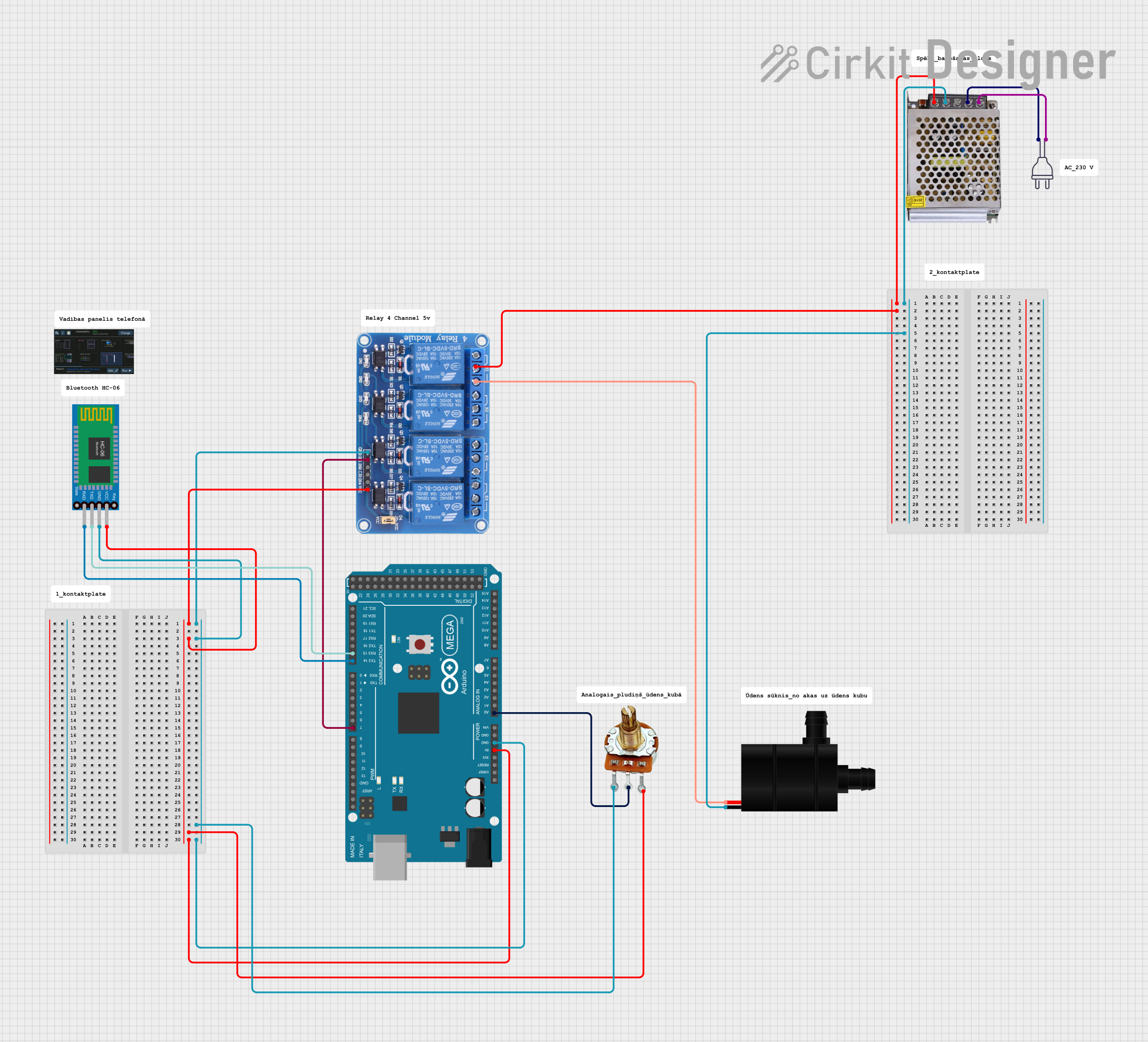
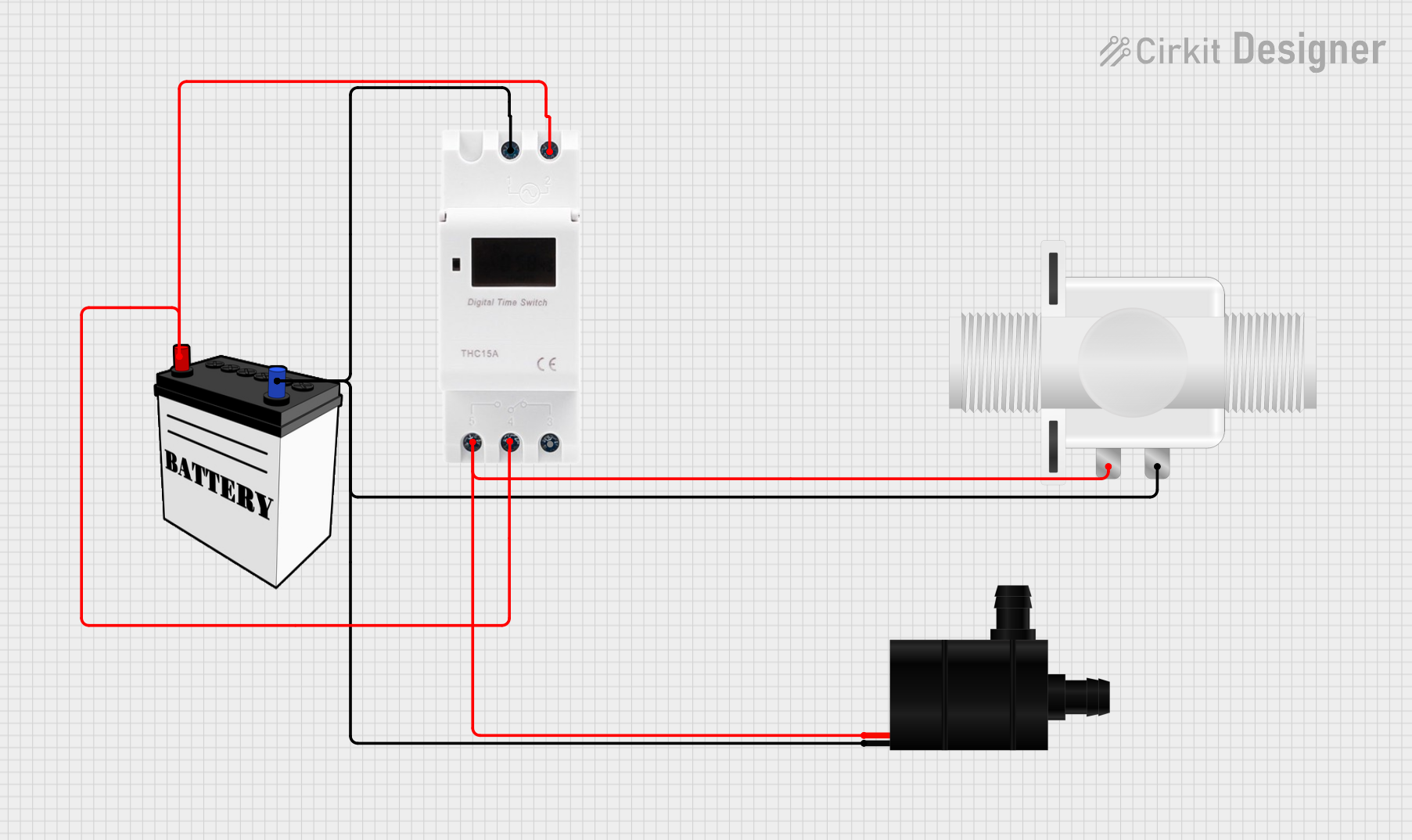
Explore Projects Built with Water pump PWM
Technical Specifications
Key Technical Details
| Parameter | Value |
|---|---|
| Voltage Range | 9V - 16V |
| Nominal Voltage | 12V |
| Maximum Current | 15A |
| Power Consumption | 180W |
| Flow Rate | Up to 9000 L/h |
| Pressure | Up to 0.8 bar |
| PWM Frequency | 100 Hz - 1 kHz |
| Operating Temperature | -40°C to +125°C |
| Weight | 1.2 kg |
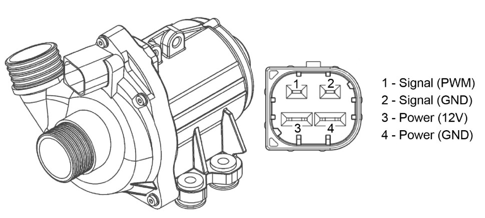
Pin Configuration and Descriptions
| Pin Number | Pin Name | Description |
|---|---|---|
| 1 | GND | Ground |
| 2 | VCC | Power Supply (9V - 16V) |
| 3 | PWM | PWM Control Signal (0V - 5V) |
| 4 | TACH | Tachometer Output (provides feedback on RPM) |
Usage Instructions
How to Use the Component in a Circuit
- Power Supply: Connect the VCC pin to a stable 12V power supply. Ensure that the power supply can provide sufficient current (up to 15A) to the pump.
- Ground Connection: Connect the GND pin to the ground of your circuit.
- PWM Control: Connect the PWM pin to a PWM-capable output of a microcontroller (e.g., Arduino UNO). The PWM signal will control the speed of the pump.
- Tachometer Feedback: Optionally, connect the TACH pin to an input pin of your microcontroller to monitor the pump's RPM.
Important Considerations and Best Practices
- PWM Signal: Ensure that the PWM signal is within the specified frequency range (100 Hz - 1 kHz) and voltage levels (0V - 5V).
- Heat Dissipation: The pump can generate significant heat during operation. Ensure adequate ventilation or cooling to prevent overheating.
- Power Supply: Use a power supply with sufficient current capacity to avoid voltage drops and ensure stable operation.
- Water Quality: Use clean water to prevent clogging and damage to the pump.
Example Arduino Code
Below is an example code to control the Pierburg CWA400 water pump using an Arduino UNO:
// Define the PWM pin connected to the pump
const int pwmPin = 9; // PWM pin 9 on Arduino UNO

void setup() {
  // Set the PWM pin as an output
  pinMode(pwmPin, OUTPUT);
}

void loop() {
  // Example: Gradually increase and decrease the pump speed
  for (int dutyCycle = 0; dutyCycle <= 255; dutyCycle++) {
    analogWrite(pwmPin, dutyCycle); // Set PWM duty cycle
    delay(10); // Wait for 10 milliseconds
  }
  for (int dutyCycle = 255; dutyCycle >= 0; dutyCycle--) {
    analogWrite(pwmPin, dutyCycle); // Set PWM duty cycle
    delay(10); // Wait for 10 milliseconds
  }
}
Troubleshooting and FAQs
Common Issues and Solutions
Pump Not Running:
- Check Power Supply: Ensure the power supply is connected and providing the correct voltage and current.
- Verify Connections: Double-check all connections, especially the ground and VCC pins.
- PWM Signal: Ensure the PWM signal is within the specified frequency and voltage range.
Pump Running at Constant Speed:
- PWM Signal: Verify that the PWM signal is being correctly generated by the microcontroller.
- Code Issues: Check the code for any errors or incorrect configurations.
Overheating:
- Ventilation: Ensure the pump has adequate ventilation or cooling.
- Continuous Operation: Avoid running the pump at maximum speed for extended periods.
FAQs
Q: Can I use a different microcontroller to control the CWA400? A: Yes, any microcontroller capable of generating a PWM signal within the specified range can be used.
Q: What type of water should I use with the CWA400? A: Use clean, filtered water to prevent clogging and damage to the pump.
Q: How do I monitor the pump's RPM? A: Connect the TACH pin to an input pin on your microcontroller and use an appropriate code to read the RPM feedback.
Q: Can the CWA400 be used in a submerged environment? A: No, the CWA400 is not designed for submerged operation. Ensure it is installed in a dry location.
By following this documentation, users can effectively integrate and utilize the Pierburg CWA400 water pump in their projects, ensuring reliable and efficient water circulation.