How to Use MAX485: Examples, Pinouts, and Specs
Introduction
The MAX485 TTL by ANMBEST is a low-power, half-duplex RS-485 transceiver designed for robust and reliable long-distance data communication. It operates over twisted pair cables and supports a maximum data rate of 2.5 Mbps, making it ideal for industrial automation, communication systems, and other applications requiring efficient data transfer. Its low power consumption and compact design make it a popular choice for embedded systems.
Explore Projects Built with MAX485


Explore Projects Built with MAX485
Common Applications
- Industrial automation and control systems
- Building automation (e.g., HVAC systems)
- Remote data acquisition
- RS-485 communication networks
- Embedded systems requiring long-distance serial communication
Technical Specifications
Key Technical Details
| Parameter | Value |
|---|---|
| Supply Voltage (Vcc) | 4.75V to 5.25V |
| Data Rate | Up to 2.5 Mbps |
| Communication Mode | Half-duplex |
| Input Voltage Range | -7V to +12V |
| Driver Output Voltage | -7V to +12V |
| Receiver Input Sensitivity | ±200 mV |
| Operating Temperature | -40°C to +85°C |
| Power Consumption | Low-power operation (300 µA idle) |
| Maximum Cable Length | Up to 1200 meters (4000 feet) |
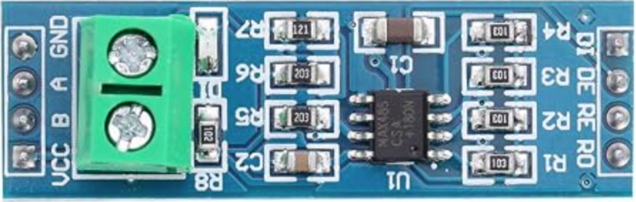
Pin Configuration and Descriptions
The MAX485 is an 8-pin IC with the following pinout:
| Pin Number | Pin Name | Description |
|---|---|---|
| 1 | RO | Receiver Output: Outputs the received data signal. |
| 2 | RE̅ | Receiver Enable: Active-low input. Enables the receiver when low. |
| 3 | DE | Driver Enable: Active-high input. Enables the driver when high. |
| 4 | DI | Driver Input: Accepts the data to be transmitted. |
| 5 | GND | Ground: Connect to the system ground. |
| 6 | A | Non-inverting Driver Output / Receiver Input (RS-485 bus line). |
| 7 | B | Inverting Driver Output / Receiver Input (RS-485 bus line). |
| 8 | Vcc | Power Supply: Connect to a 5V DC power source. |
Usage Instructions
How to Use the MAX485 in a Circuit
- Power Supply: Connect the Vcc pin to a regulated 5V DC power source and the GND pin to the system ground.
- RS-485 Bus Lines: Connect the A and B pins to the RS-485 twisted pair cable. Ensure proper termination resistors (typically 120Ω) are placed at both ends of the cable to minimize signal reflections.
- Driver and Receiver Control:
- To enable the driver, set the DE pin high.
- To enable the receiver, set the RE̅ pin low.
- For half-duplex communication, toggle these pins as needed to switch between transmitting and receiving modes.
- Data Transmission: Send data to the DI pin for transmission over the RS-485 bus. Received data will be output on the RO pin.
Important Considerations
- Termination Resistors: Always use 120Ω termination resistors at both ends of the RS-485 bus to ensure signal integrity.
- Biasing Resistors: Use pull-up and pull-down resistors on the A and B lines to maintain a known idle state when the bus is idle.
- Cable Selection: Use twisted pair cables for RS-485 communication to reduce electromagnetic interference (EMI).
- Distance and Speed: The maximum cable length decreases as the data rate increases. For example, at 2.5 Mbps, the maximum cable length is significantly shorter than the 1200-meter limit.
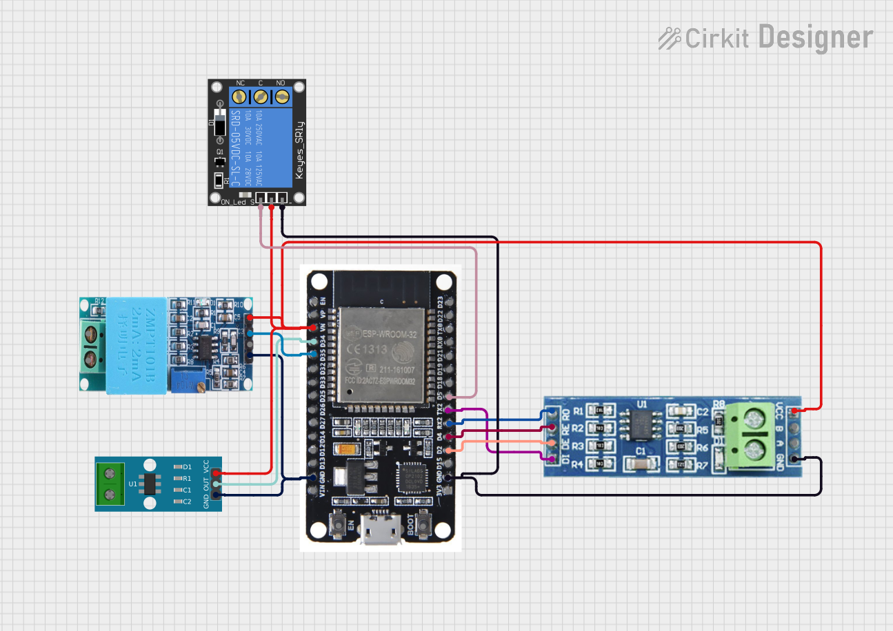
Example: Connecting MAX485 to an Arduino UNO
Below is an example of how to connect the MAX485 to an Arduino UNO for RS-485 communication:
Circuit Connections
- MAX485 Pin 8 (Vcc) → Arduino 5V
- MAX485 Pin 5 (GND) → Arduino GND
- MAX485 Pin 4 (DI) → Arduino Digital Pin 3 (TX)
- MAX485 Pin 1 (RO) → Arduino Digital Pin 2 (RX)
- MAX485 Pin 3 (DE) → Arduino Digital Pin 7
- MAX485 Pin 2 (RE̅) → Arduino Digital Pin 7
- MAX485 Pins 6 (A) and 7 (B) → RS-485 twisted pair cable
Arduino Code Example
// Include SoftwareSerial library for serial communication
#include <SoftwareSerial.h>

// Define MAX485 control pins
#define MAX485_DE 7
#define MAX485_RE 7

// Define RX and TX pins for SoftwareSerial
#define RX_PIN 2
#define TX_PIN 3

// Create a SoftwareSerial object
SoftwareSerial RS485Serial(RX_PIN, TX_PIN);

void setup() {
  // Initialize serial communication
  Serial.begin(9600);
  RS485Serial.begin(9600);

  // Set MAX485 control pins as outputs
  pinMode(MAX485_DE, OUTPUT);
  pinMode(MAX485_RE, OUTPUT);

  // Set MAX485 to receive mode initially
  digitalWrite(MAX485_DE, LOW);
  digitalWrite(MAX485_RE, LOW);

  Serial.println("RS-485 Communication Initialized");
}

void loop() {
  // Example: Send data over RS-485
  digitalWrite(MAX485_DE, HIGH); // Enable driver
  digitalWrite(MAX485_RE, HIGH); // Disable receiver
  RS485Serial.println("Hello, RS-485!");
  delay(1000);

  // Example: Receive data over RS-485
  digitalWrite(MAX485_DE, LOW); // Disable driver
  digitalWrite(MAX485_RE, LOW); // Enable receiver
  if (RS485Serial.available()) {
    String receivedData = RS485Serial.readString();
    Serial.print("Received: ");
    Serial.println(receivedData);
  }
}
Troubleshooting and FAQs
Common Issues and Solutions
No Communication on the RS-485 Bus:
- Ensure the DE and RE̅ pins are correctly toggled for transmitting and receiving.
- Verify that the RS-485 bus is properly terminated with 120Ω resistors at both ends.
Data Corruption or Noise:
- Check the cable connections and ensure twisted pair cables are used.
- Add biasing resistors to maintain a known idle state on the bus.
Short Communication Range:
- Reduce the data rate to increase the maximum cable length.
- Verify the quality of the twisted pair cable and ensure proper termination.
Overheating of the MAX485:
- Check for short circuits on the RS-485 bus lines.
- Ensure the supply voltage does not exceed the specified range (4.75V to 5.25V).
FAQs
Q1: Can the MAX485 be used for full-duplex communication?
No, the MAX485 is a half-duplex transceiver. For full-duplex communication, consider using a full-duplex RS-485 transceiver like the MAX488.
Q2: What is the maximum number of devices that can be connected to the RS-485 bus?
The MAX485 supports up to 32 devices on the RS-485 bus.
Q3: Can the MAX485 operate at 3.3V?
No, the MAX485 requires a supply voltage between 4.75V and 5.25V. For 3.3V operation, consider using a compatible RS-485 transceiver like the MAX3485.
This concludes the documentation for the MAX485 TTL by ANMBEST.