Cirkit Designer
Your all-in-one circuit design IDE
Home /
Component Documentation
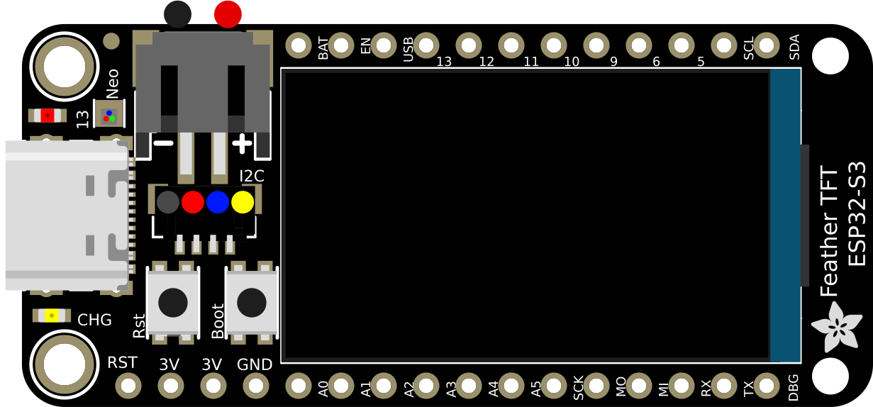
How to Use ESP32-S3 TFT Feather: Examples, Pinouts, and Specs
Introduction
The ESP32-S3 TFT Feather is a compact development board built around the ESP32-S3 microcontroller. It is specifically designed for IoT applications, offering robust processing power, integrated Wi-Fi and Bluetooth connectivity, and a built-in TFT display for visual output. This board is ideal for projects that require a combination of wireless communication, efficient processing, and a user-friendly interface.
Explore Projects Built with ESP32-S3 TFT Feather
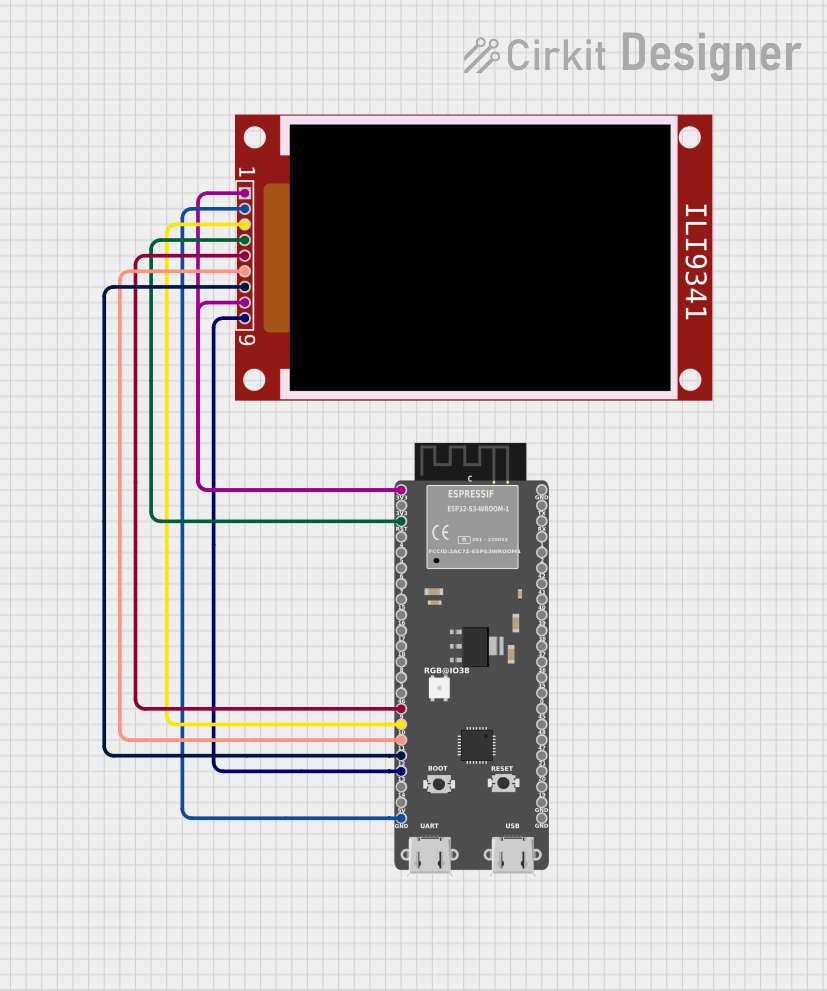
ESP32-S3 Wi-Fi Enabled ILI9341 Display for HTTP(S) Status Monitoring

This circuit integrates an ESP32-S3 microcontroller with an ILI9341 TFT display to create a Wi-Fi enabled device that fetches and displays HTTP(S) response data. The ESP32-S3 handles the network communication and controls the display, allowing for real-time visualization of data retrieved from a specified URL.
ESP32-S3 Wi-Fi Controlled ILI9341 TFT Display for Cryptocurrency Prices
This circuit integrates an ESP32-S3 microcontroller with an ILI9341 TFT display to create a WiFi-enabled cryptocurrency price viewer. The ESP32-S3 fetches real-time price data from the CoinGecko API and displays it on the TFT screen, allowing users to monitor the prices of Bitcoin, Ethereum, and Solana.
ESP32-S3 and ILI9488 TFT LCD Display for Interactive Graphics
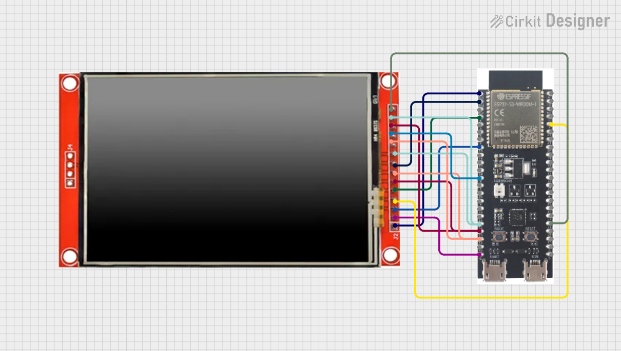
This circuit features an ESP32-S3 microcontroller connected to an ILI9488 TFT LCD display. The ESP32-S3 initializes and controls the display, demonstrating basic graphics and text rendering using the TFT_eSPI library.
ESP32-Controlled TFT LCD Display Interface
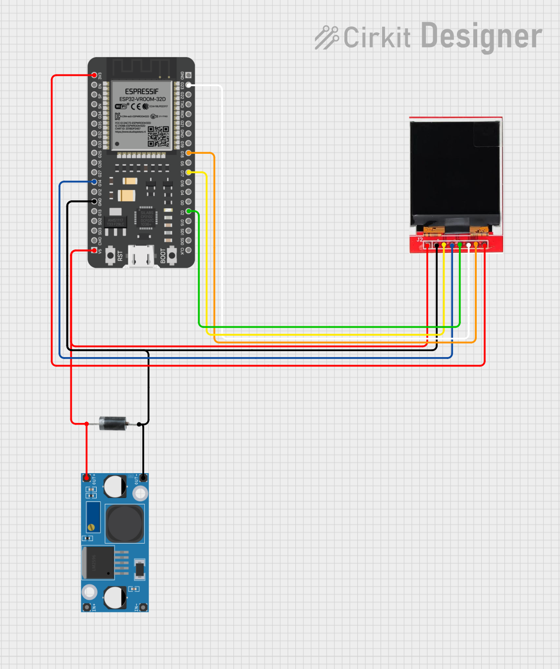
This circuit features an ESP32 microcontroller connected to a TFT LCD Display ST7735S for visual output. The ESP32 controls the display via GPIO pins, with connections for data (SDA), clock (SCK), chip select (CS), and data/command (A0). Power management is handled by an LM2956 Buck Converter, and a P6KE6.8A diode provides protection against voltage spikes.
Explore Projects Built with ESP32-S3 TFT Feather
ESP32-S3 Wi-Fi Enabled ILI9341 Display for HTTP(S) Status Monitoring
This circuit integrates an ESP32-S3 microcontroller with an ILI9341 TFT display to create a Wi-Fi enabled device that fetches and displays HTTP(S) response data. The ESP32-S3 handles the network communication and controls the display, allowing for real-time visualization of data retrieved from a specified URL.
ESP32-S3 Wi-Fi Controlled ILI9341 TFT Display for Cryptocurrency Prices
This circuit integrates an ESP32-S3 microcontroller with an ILI9341 TFT display to create a WiFi-enabled cryptocurrency price viewer. The ESP32-S3 fetches real-time price data from the CoinGecko API and displays it on the TFT screen, allowing users to monitor the prices of Bitcoin, Ethereum, and Solana.
ESP32-S3 and ILI9488 TFT LCD Display for Interactive Graphics
This circuit features an ESP32-S3 microcontroller connected to an ILI9488 TFT LCD display. The ESP32-S3 initializes and controls the display, demonstrating basic graphics and text rendering using the TFT_eSPI library.
ESP32-Controlled TFT LCD Display Interface
This circuit features an ESP32 microcontroller connected to a TFT LCD Display ST7735S for visual output. The ESP32 controls the display via GPIO pins, with connections for data (SDA), clock (SCK), chip select (CS), and data/command (A0). Power management is handled by an LM2956 Buck Converter, and a P6KE6.8A diode provides protection against voltage spikes.
Common Applications and Use Cases
- IoT devices and smart home automation
- Portable data loggers with visual feedback
- Wearable devices with graphical interfaces
- Prototyping for wireless communication systems
- Educational projects requiring a display and connectivity
Technical Specifications
Key Technical Details
- Microcontroller: ESP32-S3 (dual-core Xtensa LX7, 240 MHz)
- Flash Memory: 8 MB
- PSRAM: 2 MB
- Connectivity: Wi-Fi 802.11 b/g/n, Bluetooth 5.0 (LE)
- Display: 1.14-inch TFT LCD (240x135 resolution, ST7789 driver)
- Power Supply: 3.3V (regulated via USB-C or LiPo battery)
- GPIO Pins: 13 available for user applications
- Dimensions: 51mm x 23mm x 8mm
- Operating Voltage: 3.3V logic level
- Current Consumption: ~20mA in deep sleep, ~240mA during active use
Pin Configuration and Descriptions
| Pin Name | Type | Description |
|---|---|---|
| VIN | Power Input | Input voltage (3.7-6V) for powering the board via LiPo battery or external source. |
| 3V3 | Power Output | Regulated 3.3V output for powering external components. |
| GND | Ground | Ground connection. |
| GPIO0 | Digital I/O | General-purpose I/O pin, also used for boot mode selection. |
| GPIO1 | Digital I/O | General-purpose I/O pin. |
| GPIO2 | Digital I/O | General-purpose I/O pin. |
| GPIO3 | Digital I/O | General-purpose I/O pin. |
| GPIO4 | Digital I/O | General-purpose I/O pin. |
| GPIO5 | Digital I/O | General-purpose I/O pin. |
| SDA | I2C Data | I2C data line for communication with peripherals. |
| SCL | I2C Clock | I2C clock line for communication with peripherals. |
| MOSI | SPI Data Out | SPI Master Out Slave In (data output for SPI communication). |
| MISO | SPI Data In | SPI Master In Slave Out (data input for SPI communication). |
| SCK | SPI Clock | SPI clock line for communication. |
| TFT_CS | Digital Output | Chip select for the TFT display. |
| TFT_DC | Digital Output | Data/command control for the TFT display. |
| TFT_RST | Digital Output | Reset pin for the TFT display. |
Usage Instructions
How to Use the ESP32-S3 TFT Feather in a Circuit
- Powering the Board: Connect a USB-C cable to power the board or use a 3.7V LiPo battery via the JST connector.
- Connecting Peripherals: Use the GPIO pins for sensors, actuators, or other peripherals. Ensure the voltage levels are compatible with the 3.3V logic.
- Programming: The board can be programmed using the Arduino IDE or ESP-IDF. Install the necessary board definitions and libraries for the ESP32-S3.
- Using the TFT Display: The built-in TFT display can be controlled using the Adafruit GFX and ST7789 libraries.
Important Considerations and Best Practices
- Always use a level shifter if connecting 5V logic devices to the GPIO pins.
- Avoid drawing more than 500mA from the USB port to prevent damage.
- Use the deep sleep mode to conserve power in battery-operated projects.
- Ensure proper grounding when connecting external components to avoid noise or instability.
Example Code for Arduino IDE
Below is an example of how to display text on the TFT screen using the Adafruit GFX library:
#include <Adafruit_GFX.h>    // Core graphics library
#include <Adafruit_ST7789.h> // Driver for the TFT display
#include <SPI.h>

// Define TFT display pins
#define TFT_CS   10  // Chip select pin
#define TFT_DC   9   // Data/command pin
#define TFT_RST  8   // Reset pin

// Initialize the TFT display
Adafruit_ST7789 tft = Adafruit_ST7789(TFT_CS, TFT_DC, TFT_RST);

void setup() {
  // Initialize serial communication for debugging
  Serial.begin(115200);
  Serial.println("Initializing TFT...");

  // Initialize the TFT display
  tft.init(240, 135); // Initialize with width and height
  tft.setRotation(1); // Set display rotation
  tft.fillScreen(ST77XX_BLACK); // Clear the screen with black color

  // Display text on the screen
  tft.setTextColor(ST77XX_WHITE); // Set text color to white
  tft.setTextSize(2);             // Set text size
  tft.setCursor(10, 10);          // Set cursor position
  tft.println("Hello, ESP32-S3!"); // Print text to the screen
}

void loop() {
  // Nothing to do here
}
Troubleshooting and FAQs
Common Issues and Solutions
The board does not power on:
- Ensure the USB-C cable is properly connected and functional.
- Check the LiPo battery connection if using battery power.
Unable to upload code:
- Verify that the correct board and port are selected in the Arduino IDE.
- Hold the BOOT button while pressing the RESET button to enter bootloader mode.
TFT display shows a blank screen:
- Ensure the Adafruit GFX and ST7789 libraries are installed.
- Double-check the pin definitions in your code.
Wi-Fi or Bluetooth not working:
- Verify that the correct credentials are used for Wi-Fi.
- Ensure Bluetooth is enabled in the code and paired with the correct device.
Tips for Troubleshooting
- Use a multimeter to check voltage levels on the power and GPIO pins.
- Test the board with a simple "blink" sketch to confirm basic functionality.
- Refer to the ESP32-S3 datasheet for advanced debugging and troubleshooting.