How to Use XPT2046: Examples, Pinouts, and Specs
Introduction
The XPT2046 is a versatile touchscreen controller designed to interface with resistive touchscreens. It converts analog signals from the touchscreen into digital data, enabling precise touch input detection. This component is widely used in applications requiring user interaction, such as handheld devices, industrial control panels, and embedded systems with graphical user interfaces.
Explore Projects Built with XPT2046
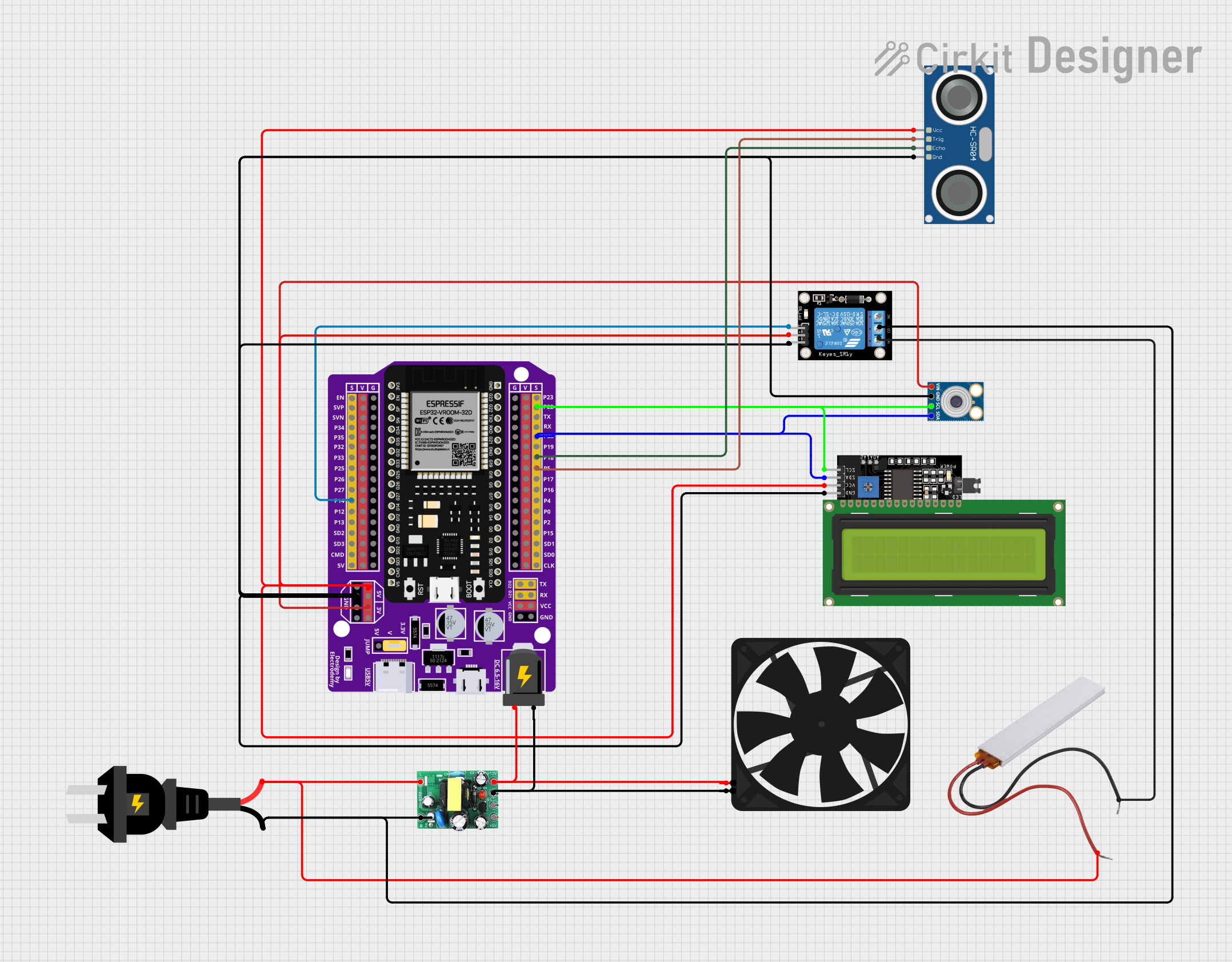


Explore Projects Built with XPT2046
Common Applications and Use Cases
- Handheld devices with touchscreens (e.g., tablets, smartphones)
- Industrial control panels and HMIs (Human-Machine Interfaces)
- Embedded systems with graphical displays
- Point-of-sale (POS) terminals
- Automotive infotainment systems
Technical Specifications
The XPT2046 is a low-power, high-performance touchscreen controller with the following key specifications:
| Parameter | Value |
|---|---|
| Operating Voltage | 2.7V to 5.5V |
| Interface | SPI (Serial Peripheral Interface) |
| Resolution | 12-bit ADC |
| Sampling Rate | Up to 125 kHz |
| Touchscreen Type | 4-wire resistive |
| Power Consumption | 0.75 mW (typical) |
| Operating Temperature | -40°C to +85°C |
Pin Configuration and Descriptions
The XPT2046 is typically available in a 16-pin TSSOP or QFN package. Below is the pinout and description:
| Pin | Name | Description |
|---|---|---|
| 1 | VCC | Power supply input (2.7V to 5.5V). |
| 2 | GND | Ground connection. |
| 3 | CS | Chip Select (active low). Enables communication with the controller. |
| 4 | DIN | Data input for SPI communication. |
| 5 | DOUT | Data output for SPI communication. |
| 6 | DCLK | Clock input for SPI communication. |
| 7 | PENIRQ | Pen interrupt output (active low). Indicates a touch event. |
| 8 | VREF | Reference voltage for the ADC. |
| 9 | X+ | X-axis positive terminal of the touchscreen. |
| 10 | Y+ | Y-axis positive terminal of the touchscreen. |
| 11 | X- | X-axis negative terminal of the touchscreen. |
| 12 | Y- | Y-axis negative terminal of the touchscreen. |
| 13-16 | NC | No connection (varies by package type). |
Usage Instructions
How to Use the XPT2046 in a Circuit
- Power Supply: Connect the VCC pin to a 3.3V or 5V power source and the GND pin to ground.
- Touchscreen Connection: Connect the X+, X-, Y+, and Y- pins to the corresponding terminals of the resistive touchscreen.
- SPI Communication:
- Connect the CS, DIN, DOUT, and DCLK pins to the SPI pins of your microcontroller.
- Ensure the SPI clock speed does not exceed the XPT2046's maximum supported rate.
- Pen Interrupt: Optionally, connect the PENIRQ pin to a GPIO pin on your microcontroller to detect touch events.
Important Considerations and Best Practices
- Voltage Levels: Ensure the logic levels of the microcontroller match the XPT2046's operating voltage.
- Noise Filtering: Add decoupling capacitors (e.g., 0.1 µF) near the VCC pin to reduce noise.
- Touchscreen Calibration: Perform calibration to map the raw ADC values to screen coordinates accurately.
- Pull-up Resistors: Use pull-up resistors on the SPI lines if required by your microcontroller.
Example Code for Arduino UNO
Below is an example of how to interface the XPT2046 with an Arduino UNO to read touch coordinates:
#include <SPI.h>

// Pin definitions
#define CS_PIN 10  // Chip Select pin
#define PENIRQ_PIN 2  // Pen interrupt pin

void setup() {
  pinMode(CS_PIN, OUTPUT);
  pinMode(PENIRQ_PIN, INPUT_PULLUP);
  SPI.begin();  // Initialize SPI communication
  Serial.begin(9600);  // Initialize serial communication for debugging
}

void loop() {
  if (digitalRead(PENIRQ_PIN) == LOW) {  // Check if the screen is touched
    digitalWrite(CS_PIN, LOW);  // Select the XPT2046
    uint16_t x = readTouchData(0x90);  // Read X-coordinate
    uint16_t y = readTouchData(0xD0);  // Read Y-coordinate
    digitalWrite(CS_PIN, HIGH);  // Deselect the XPT2046

    Serial.print("X: ");
    Serial.print(x);
    Serial.print(", Y: ");
    Serial.println(y);
  }
  delay(100);  // Small delay for stability
}

// Function to read touch data from the XPT2046
uint16_t readTouchData(uint8_t command) {
  SPI.beginTransaction(SPISettings(2000000, MSBFIRST, SPI_MODE0));
  SPI.transfer(command);  // Send command to XPT2046
  uint16_t data = SPI.transfer(0x00) << 8;  // Read high byte
  data |= SPI.transfer(0x00);  // Read low byte
  SPI.endTransaction();
  return data >> 3;  // Return 12-bit result (shift right by 3 bits)
}
Troubleshooting and FAQs
Common Issues and Solutions
No Response from the XPT2046:
- Ensure the CS pin is correctly connected and toggled during SPI communication.
- Verify the SPI clock speed is within the supported range.
Incorrect Touch Coordinates:
- Perform touchscreen calibration to map raw ADC values to screen coordinates.
- Check for loose or incorrect connections to the touchscreen terminals.
No Pen Interrupt Signal:
- Ensure the PENIRQ pin is connected to a GPIO pin configured as an input.
- Verify the touchscreen is properly connected and functional.
Noise or Unstable Readings:
- Add decoupling capacitors near the VCC pin to filter power supply noise.
- Use shielded cables or minimize the length of signal wires.
FAQs
Q: Can the XPT2046 work with a 5V microcontroller?
A: Yes, the XPT2046 supports operating voltages from 2.7V to 5.5V, making it compatible with 5V microcontrollers like the Arduino UNO.
Q: How do I calibrate the touchscreen?
A: Calibration involves mapping the raw ADC values to screen coordinates. This can be done by touching known points on the screen and using a calibration algorithm to calculate the mapping.
Q: What is the maximum SPI clock speed for the XPT2046?
A: The XPT2046 supports SPI clock speeds up to 2 MHz. Ensure your microcontroller's SPI settings do not exceed this limit.