How to Use joule meter: Examples, Pinouts, and Specs
Introduction
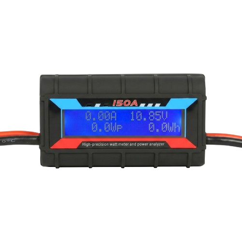
A joule meter is an electronic instrument designed to measure energy in joules. It is commonly used in experiments and applications where quantifying energy transfer or consumption is critical. Joule meters are particularly useful in electrical circuits to monitor energy usage, efficiency, and power consumption over time. They are widely employed in educational labs, research facilities, and industrial environments.
Explore Projects Built with joule meter
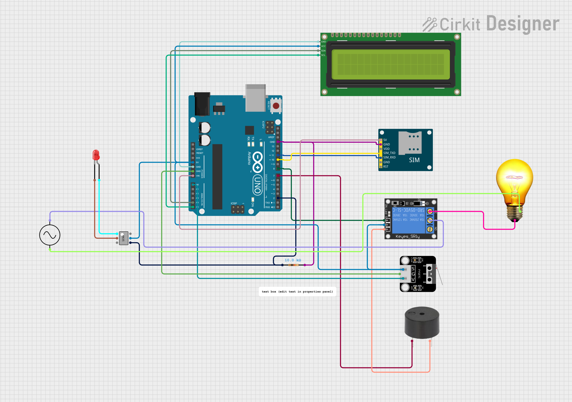
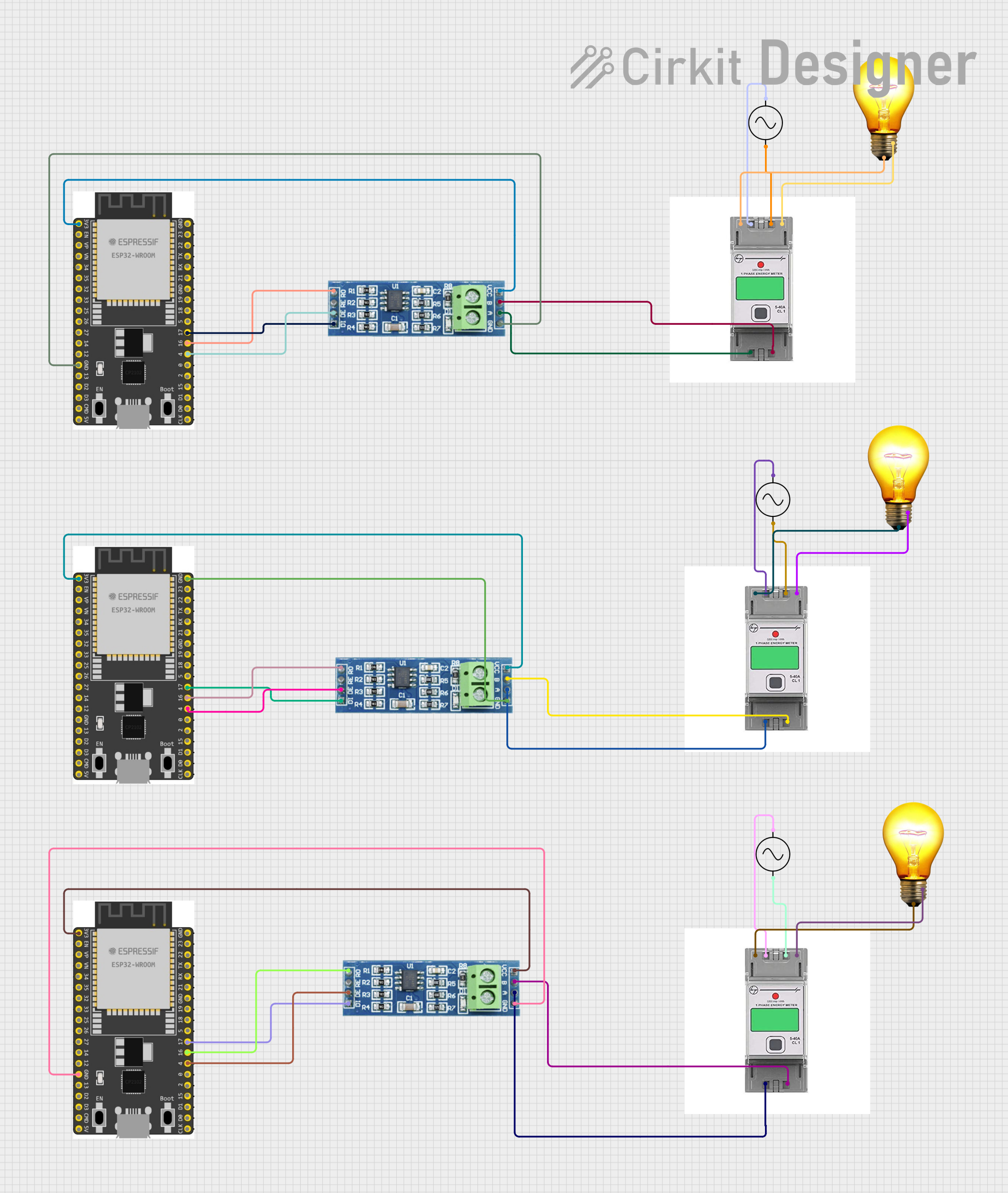
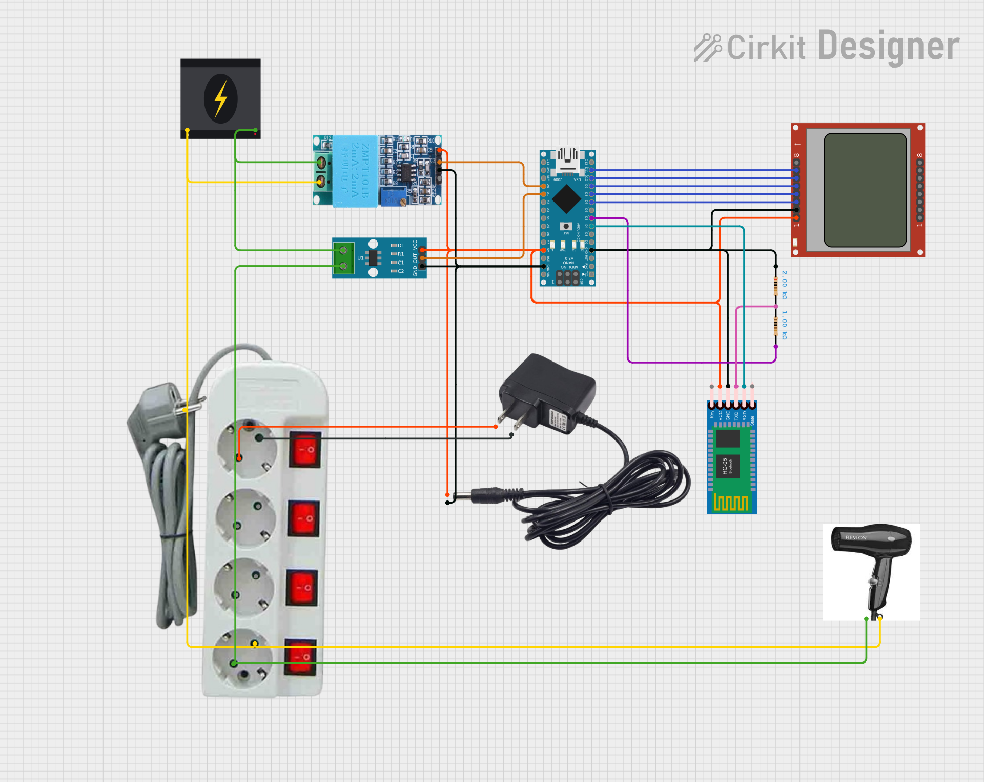
Explore Projects Built with joule meter
Common Applications and Use Cases
- Measuring energy consumption in electrical devices and circuits.
- Monitoring energy transfer in renewable energy systems (e.g., solar panels).
- Evaluating the efficiency of motors, heaters, and other appliances.
- Educational experiments to demonstrate energy principles.
- Industrial energy audits and optimization.
Technical Specifications
Below are the key technical details for a typical joule meter:
| Parameter | Specification |
|---|---|
| Input Voltage Range | 3.3V to 30V DC |
| Current Measurement Range | 0A to 10A |
| Energy Measurement Range | 0 to 999,999 Joules |
| Accuracy | ±1% |
| Display Type | LCD or OLED (varies by model) |
| Communication Interface | I2C, UART, or SPI (optional, model-specific) |
| Power Supply | 5V DC (via USB or external power source) |
| Operating Temperature | -10°C to 60°C |
Pin Configuration and Descriptions
The pinout of a joule meter may vary depending on the model. Below is a general pin configuration for a joule meter with an I2C interface:
| Pin Name | Description |
|---|---|
| VCC | Power supply input (typically 5V DC) |
| GND | Ground connection |
| SDA | I2C data line |
| SCL | I2C clock line |
| VIN+ | Positive voltage input for energy measurement |
| VIN- | Negative voltage input for energy measurement |
| I+ | Positive current input for energy measurement |
| I- | Negative current input for energy measurement |
Usage Instructions
How to Use the Component in a Circuit
- Power the Joule Meter: Connect the VCC and GND pins to a 5V DC power source.
- Connect Voltage Input: Attach the VIN+ and VIN- pins across the voltage source you want to measure.
- Connect Current Input: Pass the current-carrying wire through the I+ and I- terminals to measure current.
- Read Energy Data: Use the built-in display to view energy readings or connect the joule meter to a microcontroller (e.g., Arduino UNO) via the I2C interface for data logging.
Important Considerations and Best Practices
- Ensure the input voltage and current do not exceed the specified ranges to avoid damage.
- Use proper wiring and secure connections to minimize noise and ensure accurate readings.
- If using the I2C interface, ensure pull-up resistors are connected to the SDA and SCL lines.
- Calibrate the joule meter periodically for optimal accuracy.
- Avoid exposing the device to extreme temperatures or humidity.
Example: Connecting to an Arduino UNO
Below is an example of how to interface a joule meter with an Arduino UNO using the I2C protocol:
#include <Wire.h>

// Define the I2C address of the joule meter (replace with your device's address)
#define JOULE_METER_ADDR 0x40

void setup() {
  Wire.begin(); // Initialize I2C communication
  Serial.begin(9600); // Start serial communication for debugging

  // Optional: Send initialization commands to the joule meter if required
  Serial.println("Joule Meter Initialized");
}

void loop() {
  Wire.beginTransmission(JOULE_METER_ADDR); // Start communication with joule meter
  Wire.write(0x00); // Request energy data (register address may vary by model)
  Wire.endTransmission();

  Wire.requestFrom(JOULE_METER_ADDR, 4); // Request 4 bytes of energy data
  if (Wire.available() == 4) {
    uint32_t energy = 0;
    for (int i = 0; i < 4; i++) {
      energy = (energy << 8) | Wire.read(); // Combine bytes into a 32-bit value
    }
    Serial.print("Energy: ");
    Serial.print(energy);
    Serial.println(" Joules");
  }

  delay(1000); // Wait 1 second before the next reading
}
Troubleshooting and FAQs
Common Issues Users Might Face
No Display or Readings:
- Ensure the joule meter is powered correctly (check VCC and GND connections).
- Verify that the input voltage and current are within the specified ranges.
Inaccurate Measurements:
- Check for loose or noisy connections.
- Calibrate the joule meter if readings are consistently off.
I2C Communication Failure:
- Confirm the I2C address of the joule meter matches the code.
- Ensure pull-up resistors are connected to the SDA and SCL lines.
- Check for conflicting devices on the I2C bus.
Solutions and Tips for Troubleshooting
- Use a multimeter to verify input voltage and current before connecting the joule meter.
- Double-check all wiring and connections for proper polarity and secure attachment.
- Refer to the manufacturer's datasheet for model-specific details and troubleshooting steps.
- If using a microcontroller, test the I2C bus with a simple scanner sketch to detect the joule meter's address.
By following this documentation, users can effectively integrate and utilize a joule meter in their projects for accurate energy measurement and monitoring.