How to Use Reciver: Examples, Pinouts, and Specs
Introduction
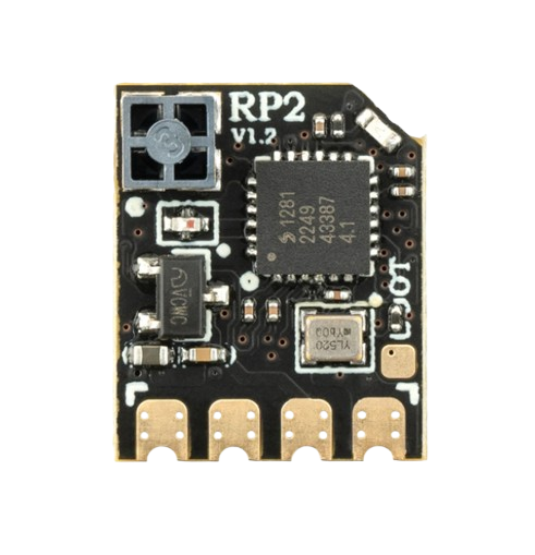
The Radio Master RP2 Receiver is a versatile electronic component designed to capture and convert transmitted signals into a usable form. It is commonly used in communication systems to decode information sent over various transmission mediums, such as radio frequency (RF) signals. The RP2 is ideal for applications requiring reliable signal reception, including remote controls, wireless communication systems, and telemetry devices.
Explore Projects Built with Reciver


Explore Projects Built with Reciver
Common Applications and Use Cases
- Wireless communication systems (e.g., RF modules, IoT devices)
- Remote control systems (e.g., drones, RC cars, and planes)
- Telemetry and data acquisition systems
- Signal decoding in industrial and consumer electronics
Technical Specifications
The RP2 Receiver is designed to operate efficiently in a wide range of environments. Below are its key technical specifications:
| Parameter | Value |
|---|---|
| Manufacturer | Radio Master |
| Part ID | RP2 |
| Operating Voltage | 3.3V to 5.5V |
| Operating Current | 10 mA (typical) |
| Frequency Range | 315 MHz to 433 MHz |
| Sensitivity | -105 dBm |
| Data Rate | Up to 10 kbps |
| Operating Temperature | -20°C to +70°C |
| Dimensions | 30 mm x 15 mm x 5 mm |
Pin Configuration and Descriptions
The RP2 Receiver has a simple 4-pin configuration, as detailed below:
| Pin | Name | Description |
|---|---|---|
| 1 | VCC | Power supply input (3.3V to 5.5V). Connect to the positive terminal of the power source. |
| 2 | GND | Ground. Connect to the ground of the power source or circuit. |
| 3 | DATA | Output pin for the decoded signal. Connect to a microcontroller or processing unit. |
| 4 | ANT | Antenna input. Connect to an external antenna for signal reception. |
Usage Instructions
The RP2 Receiver is straightforward to integrate into a circuit. Follow the steps below to ensure proper operation:
Connecting the RP2 Receiver
- Power Supply: Connect the VCC pin to a 3.3V to 5.5V power source and the GND pin to the ground.
- Signal Output: Connect the DATA pin to the input pin of a microcontroller or other processing unit.
- Antenna: Attach an appropriate antenna to the ANT pin to improve signal reception. Ensure the antenna is tuned to the operating frequency range (315 MHz to 433 MHz).
Important Considerations
- Antenna Selection: Use a high-quality antenna designed for the operating frequency range to maximize signal reception.
- Noise Reduction: Place decoupling capacitors (e.g., 0.1 µF) near the VCC and GND pins to reduce noise and improve stability.
- Signal Decoding: The RP2 outputs raw data on the DATA pin. Use a microcontroller or decoder IC to process the signal.
- Placement: Avoid placing the receiver near high-frequency noise sources, such as switching power supplies, to prevent interference.
Example: Using RP2 with Arduino UNO
Below is an example of how to connect and use the RP2 Receiver with an Arduino UNO to decode signals:
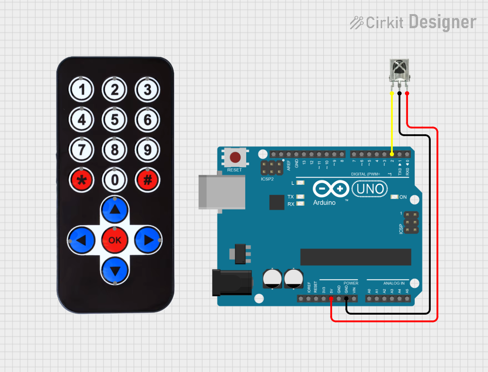
Circuit Diagram
- Connect the RP2's VCC pin to the Arduino's 5V pin.
- Connect the RP2's GND pin to the Arduino's GND pin.
- Connect the RP2's DATA pin to Arduino digital pin 2.
- Attach an antenna to the RP2's ANT pin.
Arduino Code
// Example code to read data from the RP2 Receiver using Arduino UNO
// Connect the RP2 DATA pin to Arduino digital pin 2

#define DATA_PIN 2  // Define the pin connected to the RP2 DATA pin

void setup() {
  Serial.begin(9600);  // Initialize serial communication at 9600 baud
  pinMode(DATA_PIN, INPUT);  // Set the DATA pin as input
}

void loop() {
  int signal = digitalRead(DATA_PIN);  // Read the signal from the RP2
  Serial.println(signal);  // Print the signal to the Serial Monitor

  delay(10);  // Small delay to stabilize readings
}
Best Practices
- Use a regulated power supply to ensure stable operation.
- Keep the antenna away from metallic objects to avoid signal attenuation.
- If using the RP2 in a noisy environment, consider adding a low-pass filter to the DATA pin.
Troubleshooting and FAQs
Common Issues and Solutions
No Signal Output on DATA Pin
- Cause: Poor antenna connection or incorrect frequency.
- Solution: Ensure the antenna is securely connected and tuned to the correct frequency range.
Intermittent Signal Reception
- Cause: Electrical noise or interference.
- Solution: Add decoupling capacitors near the power pins and move the receiver away from noise sources.
Weak Signal Strength
- Cause: Inadequate antenna or obstructions.
- Solution: Use a higher-quality antenna and ensure a clear line of sight to the transmitter.
High Power Consumption
- Cause: Incorrect operating voltage.
- Solution: Verify that the power supply voltage is within the specified range (3.3V to 5.5V).
FAQs
Q: Can the RP2 Receiver be used with 3.3V microcontrollers?
A: Yes, the RP2 operates within a voltage range of 3.3V to 5.5V, making it compatible with 3.3V microcontrollers.
Q: What type of antenna should I use with the RP2?
A: Use a whip or helical antenna tuned to the operating frequency range (315 MHz to 433 MHz) for optimal performance.
Q: Does the RP2 support multiple frequencies?
A: The RP2 is designed to operate within the 315 MHz to 433 MHz range. Ensure the transmitter and receiver are on the same frequency.
Q: How do I decode the signal from the DATA pin?
A: Use a microcontroller or dedicated decoder IC to process the raw data output from the DATA pin.
By following this documentation, you can effectively integrate and troubleshoot the Radio Master RP2 Receiver in your projects.