How to Use Safety Relay: Examples, Pinouts, and Specs
Introduction
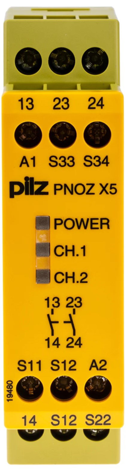
The PNOZ X5 2NO safety relay by Pilz is an essential component in industrial safety circuits. It is designed to monitor various safety devices such as emergency stop buttons, safety gates, and light curtains. When a hazardous condition is detected, the safety relay will initiate a reliable and immediate shutdown of machinery to protect both personnel and equipment.
Explore Projects Built with Safety Relay


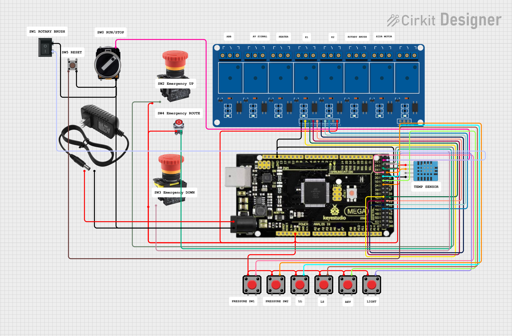
Explore Projects Built with Safety Relay
Common Applications and Use Cases
- Emergency stop circuits
- Safety gate monitoring
- Light curtain integration
- Two-hand control stations
- Monitoring of safety mats and edges
Technical Specifications
Key Technical Details
- Supply Voltage: 24 VDC or 24 VAC, 50/60 Hz
- Output Contacts: 2 NO (Normally Open)
- Contact Material: Silver alloy
- Contact Rating: 240 VAC, 6 A
- Safety Integrity Level (SIL): SIL3
- Performance Level (PL): PL e according to EN ISO 13849-1
- Response Time: ≤ 20 ms
- Terminal Type: Screw terminals
Pin Configuration and Descriptions
| Pin Number | Description | Notes |
|---|---|---|
| A1, A2 | Supply Voltage | Connect to 24 VDC or 24 VAC |
| S11, S12 | Input Signal | Connect to safety device output |
| S21, S22 | Reset Circuit | Connect to reset button/output |
| 13, 14 | Safety Output Contact 1 (NO) | Load connection |
| 23, 24 | Safety Output Contact 2 (NO) | Load connection |
| 31, 32 | Auxiliary Output (NC) | Diagnostic purposes |
Usage Instructions
How to Use the Component in a Circuit
- Power Supply Connection: Connect the supply voltage to terminals A1 and A2. Ensure the voltage matches the relay's specification.
- Safety Device Integration: Connect the output of the safety device (e.g., E-STOP) to terminals S11 and S12.
- Reset Function: If a manual reset is required, connect a normally closed reset button to terminals S21 and S22.
- Load Connection: Connect the load that needs to be controlled in case of a safety event to the safety output contacts (terminals 13-14 and 23-24).
Important Considerations and Best Practices
- Always ensure that the power supply matches the relay's voltage specifications.
- Regularly test the safety relay and connected safety devices to ensure proper operation.
- Use appropriate cable sizes and terminal torques as specified by the manufacturer.
- Do not exceed the contact ratings to prevent premature failure of the relay.
- Ensure proper grounding of the relay and the control system for safety and noise immunity.
Troubleshooting and FAQs
Common Issues
- Relay Not Activating: Check the supply voltage and connections to the safety devices. Ensure that the safety devices are functioning correctly.
- Relay Not Resetting: Verify that the reset circuit is connected properly and that the reset button is operational.
- False Tripping: Inspect the wiring for shorts or interference. Ensure that the safety devices are not being triggered unintentionally.
Solutions and Tips for Troubleshooting
- Double-check all wiring connections according to the pin configuration.
- Measure the supply voltage to ensure it is within the specified range.
- Test the functionality of connected safety devices independently.
- If the relay is not resetting, check for continuity across the reset button when pressed.
FAQs
Q: Can the PNOZ X5 2NO be used for monitoring multiple safety devices? A: Yes, it can monitor multiple devices, but they must be wired in series to ensure that any single fault will result in a stop command.
Q: What should I do if the relay contacts are welded? A: This is typically a result of overloading the contacts. Replace the relay and ensure the load does not exceed the specified ratings.
Q: How often should the safety relay be tested? A: Regular testing intervals should be established according to the operational environment and usage frequency. Refer to the manufacturer's recommendations for specific guidelines.
Note: This documentation is for informational purposes only. Always consult the manufacturer's manual and safety guidelines when installing and operating the safety relay.