
How to Use LSM303DLH: Examples, Pinouts, and Specs
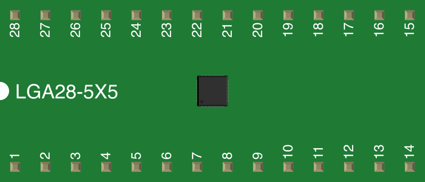
 Design with LSM303DLH in Cirkit Designer
Introduction
The LSM303DLH is a compact, high-performance 3-axis accelerometer and 3-axis magnetometer sensor. It is designed for motion and orientation detection, making it ideal for applications such as smartphones, tablets, wearable devices, and gaming peripherals. The sensor provides digital output via I2C or SPI interfaces, allowing seamless integration with microcontroller-based systems. Its small size, low power consumption, and high accuracy make it a popular choice for embedded systems requiring precise motion and orientation data.
Explore Projects Built with LSM303DLH
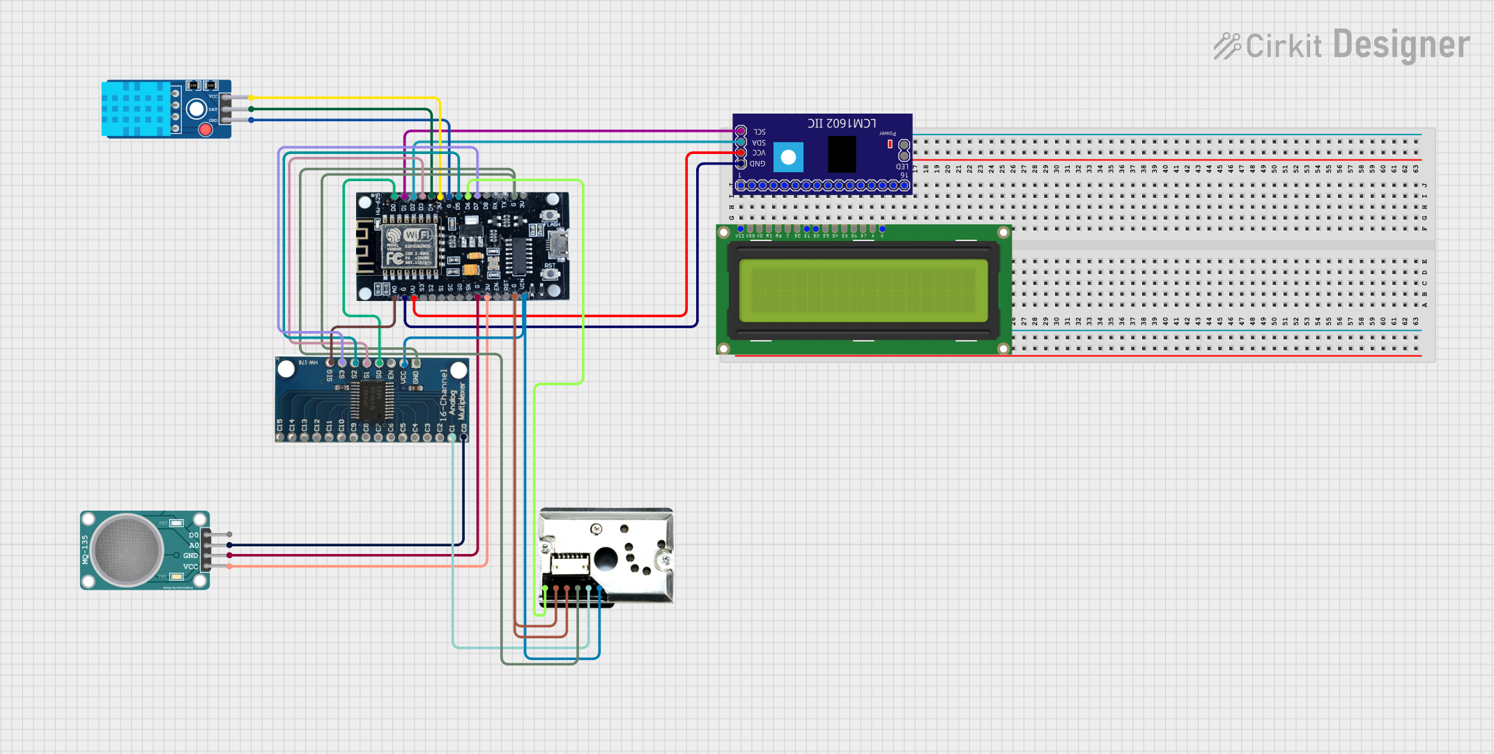 Open Project in Cirkit Designer
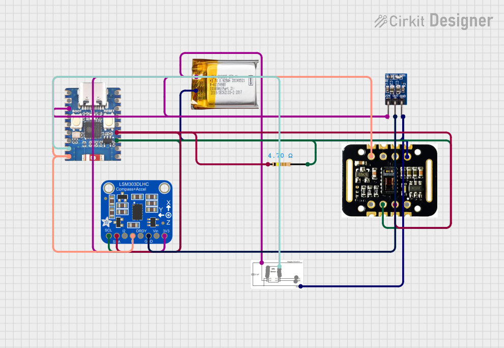 Open Project in Cirkit Designer
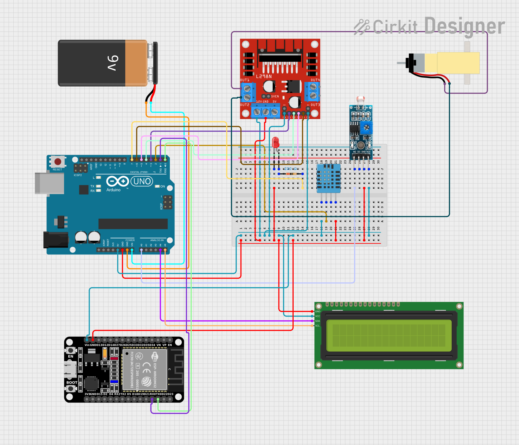 Open Project in Cirkit Designer
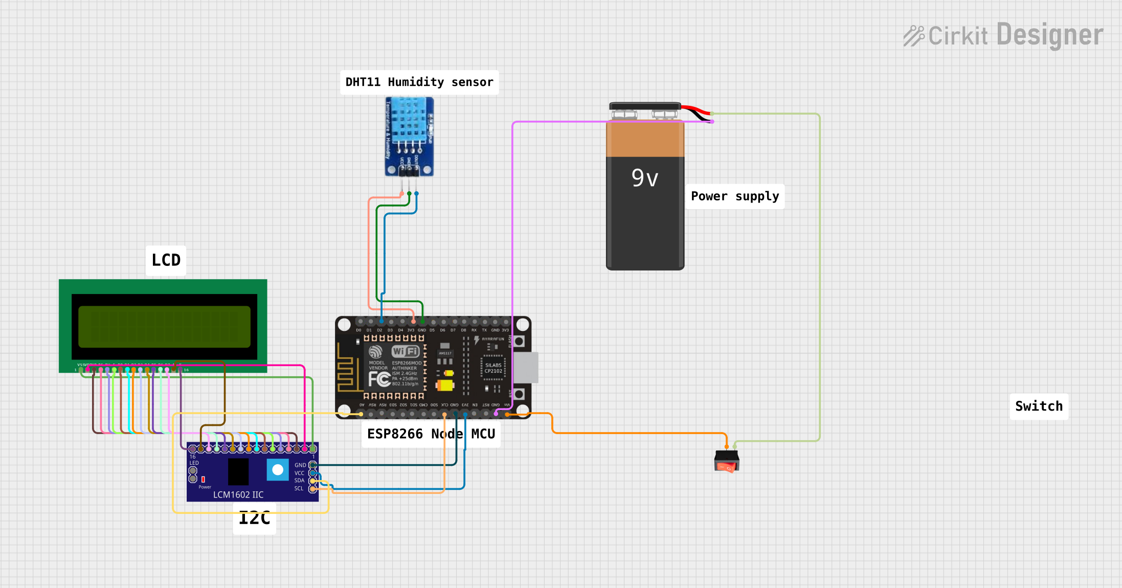 Open Project in Cirkit Designer
Explore Projects Built with LSM303DLH
Open Project in Cirkit DesignerOpen Project in Cirkit DesignerOpen Project in Cirkit DesignerOpen Project in Cirkit DesignerCommon Applications
- Motion tracking in smartphones and tablets
- Orientation detection in wearable devices
- Navigation systems (e.g., electronic compasses)
- Gaming peripherals for motion-based controls
- Robotics and drone stabilization
Technical Specifications
Key Technical Details
| Parameter | Value |
|---|---|
| Accelerometer Range | ±2g, ±4g, ±8g |
| Magnetometer Range | ±1.3 to ±8.1 gauss |
| Output Interface | I2C (up to 400 kHz) or SPI (up to 10 MHz) |
| Operating Voltage | 2.16V to 3.6V |
| Current Consumption | Accelerometer: 200 µA, Magnetometer: 110 µA |
| Operating Temperature | -40°C to +85°C |
| Sensitivity (Accelerometer) | 1 mg/LSB (±2g range) |
| Sensitivity (Magnetometer) | 1100 LSB/gauss (±1.3 gauss range) |
| Package Size | 3x5x1 mm LGA-16 |
Pin Configuration and Descriptions
The LSM303DLH is housed in a 16-pin LGA package. Below is the pin configuration:
| Pin Number | Pin Name | Description |
|---|---|---|
| 1 | VDD | Supply voltage (2.16V to 3.6V) |
| 2 | GND | Ground |
| 3 | SCL/SPC | I2C clock line / SPI clock |
| 4 | SDA/SDI/SDO | I2C data line / SPI data input/output |
| 5 | DRDY | Data ready signal (optional) |
| 6 | INT1 | Interrupt 1 output |
| 7 | INT2 | Interrupt 2 output |
| 8 | CS | SPI chip select (active low) |
| 9-16 | NC | Not connected |
Usage Instructions
How to Use the LSM303DLH in a Circuit
- Power Supply: Connect the VDD pin to a 2.16V-3.6V power source and the GND pin to ground.
- Interface Selection: Choose between I2C or SPI communication:
- For I2C, connect the SCL and SDA pins to the corresponding microcontroller pins with pull-up resistors (typically 4.7 kΩ).
- For SPI, connect the SPC, SDI/SDO, and CS pins to the microcontroller's SPI interface.
- Interrupts: Optionally, connect INT1 and INT2 pins to microcontroller GPIOs for event-driven applications.
- Initialization: Configure the sensor's registers via the chosen communication interface to set the desired operating mode, range, and data rate.
Important Considerations and Best Practices
- Use decoupling capacitors (e.g., 0.1 µF) near the VDD pin to reduce noise.
- Ensure proper pull-up resistors are used for I2C communication.
- Avoid placing the sensor near strong magnetic fields or vibrations to maintain accuracy.
- Calibrate the magnetometer to account for hard and soft iron distortions in the environment.
Example Code for Arduino UNO (I2C Interface)
Below is an example of how to interface the LSM303DLH with an Arduino UNO using the I2C interface:
#include <Wire.h>

// LSM303DLH I2C address
#define LSM303_ACC_ADDR  0x19  // Accelerometer address
#define LSM303_MAG_ADDR  0x1E  // Magnetometer address

void setup() {
  Wire.begin(); // Initialize I2C communication
  Serial.begin(9600); // Initialize serial communication for debugging

  // Initialize accelerometer
  Wire.beginTransmission(LSM303_ACC_ADDR);
  Wire.write(0x20); // CTRL_REG1_A: Enable accelerometer
  Wire.write(0x27); // 10 Hz, normal mode, all axes enabled
  Wire.endTransmission();

  // Initialize magnetometer
  Wire.beginTransmission(LSM303_MAG_ADDR);
  Wire.write(0x00); // CRA_REG_M: Set data rate to 15 Hz
  Wire.write(0x14); // 15 Hz output rate
  Wire.endTransmission();
}

void loop() {
  int16_t accX, accY, accZ;
  int16_t magX, magY, magZ;

  // Read accelerometer data
  Wire.beginTransmission(LSM303_ACC_ADDR);
  Wire.write(0x28 | 0x80); // OUT_X_L_A with auto-increment
  Wire.endTransmission();
  Wire.requestFrom(LSM303_ACC_ADDR, 6);
  accX = Wire.read() | (Wire.read() << 8);
  accY = Wire.read() | (Wire.read() << 8);
  accZ = Wire.read() | (Wire.read() << 8);

  // Read magnetometer data
  Wire.beginTransmission(LSM303_MAG_ADDR);
  Wire.write(0x03); // OUT_X_H_M register
  Wire.endTransmission();
  Wire.requestFrom(LSM303_MAG_ADDR, 6);
  magX = (Wire.read() << 8) | Wire.read();
  magY = (Wire.read() << 8) | Wire.read();
  magZ = (Wire.read() << 8) | Wire.read();

  // Print data to serial monitor
  Serial.print("Acc: ");
  Serial.print(accX); Serial.print(", ");
  Serial.print(accY); Serial.print(", ");
  Serial.print(accZ); Serial.print(" | Mag: ");
  Serial.print(magX); Serial.print(", ");
  Serial.print(magY); Serial.print(", ");
  Serial.println(magZ);

  delay(500); // Delay for readability
}
Troubleshooting and FAQs
Common Issues
No Data Output:
- Ensure the sensor is powered correctly (check VDD and GND connections).
- Verify the I2C or SPI connections and addresses.
- Check if the sensor is properly initialized (register configuration).
Inaccurate Readings:
- Calibrate the magnetometer to account for environmental distortions.
- Ensure the sensor is mounted securely to avoid vibrations.
Communication Errors:
- Check pull-up resistors on the I2C lines.
- Verify the SPI clock speed does not exceed 10 MHz.
Solutions and Tips
- Use a logic analyzer or oscilloscope to debug communication issues.
- Refer to the LSM303DLH datasheet for detailed register descriptions.
- If using I2C, ensure no address conflicts with other devices on the bus.
By following this documentation, users can effectively integrate the LSM303DLH into their projects for reliable motion and orientation sensing.