How to Use Display Lcd Tfl 2.0 ips spi: Examples, Pinouts, and Specs
Introduction
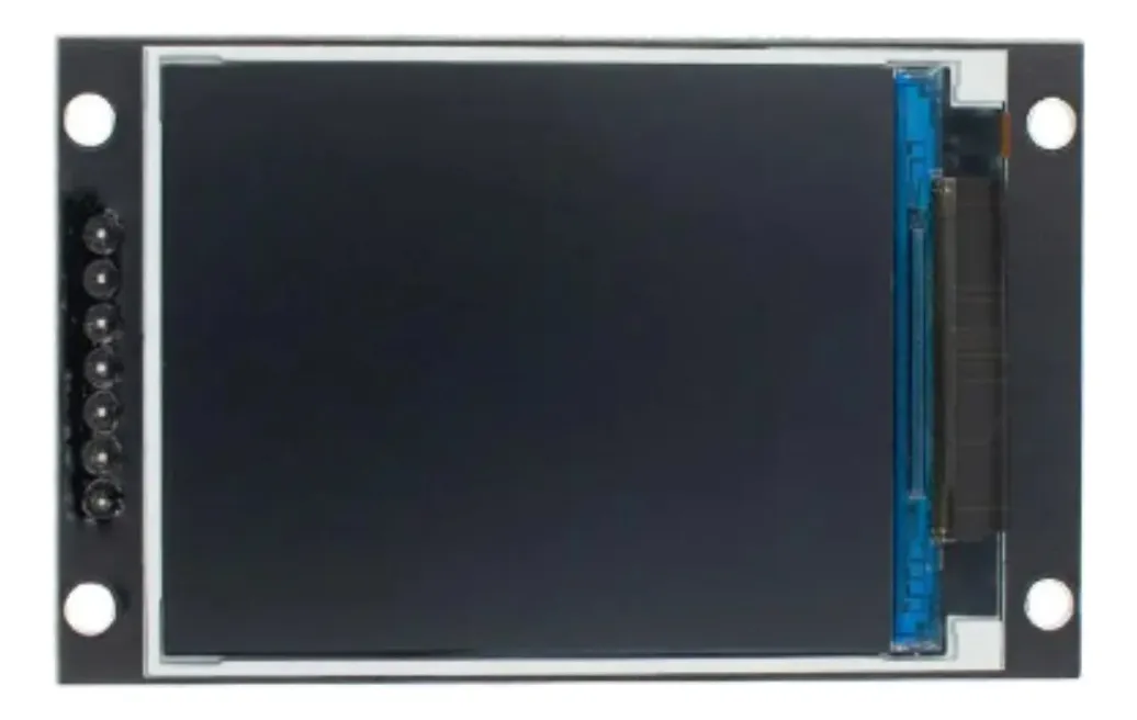
The Display LCD TFT 2.0 IPS SPI (Part ID: GMT020-02) is a 2.0-inch LCD module that utilizes TFT (Thin-Film Transistor) technology to deliver vibrant colors and wide viewing angles. It features an IPS (In-Plane Switching) panel for enhanced color accuracy and consistency, making it ideal for applications requiring high-quality visual output. The module communicates via the SPI (Serial Peripheral Interface) protocol, ensuring fast and efficient data transfer.
Explore Projects Built with Display Lcd Tfl 2.0 ips spi

Explore Projects Built with Display Lcd Tfl 2.0 ips spi
Common Applications and Use Cases
- Embedded systems and IoT devices
- Handheld devices and portable displays
- Industrial control panels
- Consumer electronics (e.g., smart home devices, wearables)
- Prototyping and educational projects
Technical Specifications
Below are the key technical details of the GMT020-02 display module:
| Parameter | Value |
|---|---|
| Display Type | TFT LCD with IPS technology |
| Screen Size | 2.0 inches |
| Resolution | 240 x 320 pixels |
| Interface | SPI (Serial Peripheral Interface) |
| Operating Voltage | 3.3V |
| Backlight Voltage | 3.0V to 3.6V |
| Backlight Current | 20mA (typical) |
| Viewing Angle | 160° (horizontal and vertical) |
| Operating Temperature | -20°C to 70°C |
| Storage Temperature | -30°C to 80°C |
Pin Configuration and Descriptions
The GMT020-02 module has the following pinout:
| Pin Number | Pin Name | Description |
|---|---|---|
| 1 | GND | Ground connection |
| 2 | VCC | Power supply (3.3V) |
| 3 | SCL | SPI clock signal |
| 4 | SDA | SPI data signal |
| 5 | RES | Reset pin (active low) |
| 6 | DC | Data/Command control pin |
| 7 | CS | Chip select (active low) |
| 8 | BLK | Backlight control (connect to 3.3V for always on) |
Usage Instructions
How to Use the Component in a Circuit
- Power Supply: Connect the VCC pin to a 3.3V power source and the GND pin to ground.
- SPI Communication: Connect the SCL (clock) and SDA (data) pins to the corresponding SPI pins on your microcontroller.
- Control Pins:
- Connect the RES pin to a GPIO pin on your microcontroller for resetting the display.
- Use the DC pin to toggle between data and command modes.
- The CS pin should be connected to a GPIO pin to enable or disable the display.
- Backlight: Connect the BLK pin to 3.3V for constant backlight or to a PWM pin for brightness control.
Important Considerations and Best Practices
- Voltage Levels: Ensure all input signals are at 3.3V logic levels. Use level shifters if your microcontroller operates at 5V.
- Reset Sequence: Always perform a hardware reset using the RES pin during initialization.
- SPI Speed: Configure the SPI clock speed according to the display's datasheet (typically up to 10 MHz).
- Backlight Control: Use a PWM signal to adjust the backlight brightness for power efficiency.
Example Code for Arduino UNO
Below is an example of how to interface the GMT020-02 display with an Arduino UNO using the SPI protocol. Note that a 5V-to-3.3V level shifter is required for compatibility.
#include <SPI.h>
#include <Adafruit_GFX.h>    // Graphics library
#include <Adafruit_ILI9341.h> // Driver for TFT displays

// Pin definitions
#define TFT_CS   10  // Chip select pin
#define TFT_DC   9   // Data/Command pin
#define TFT_RST  8   // Reset pin

// Initialize the display object
Adafruit_ILI9341 tft = Adafruit_ILI9341(TFT_CS, TFT_DC, TFT_RST);

void setup() {
  // Initialize serial communication for debugging
  Serial.begin(9600);
  Serial.println("Initializing display...");

  // Initialize the display
  tft.begin();
  tft.setRotation(1); // Set display orientation (1 = landscape)

  // Clear the screen with a black background
  tft.fillScreen(ILI9341_BLACK);

  // Display a welcome message
  tft.setTextColor(ILI9341_WHITE);
  tft.setTextSize(2);
  tft.setCursor(10, 10);
  tft.println("Hello, World!");
}

void loop() {
  // Example: Draw a red rectangle
  tft.fillRect(50, 50, 100, 50, ILI9341_RED);
  delay(1000);

  // Example: Clear the rectangle
  tft.fillRect(50, 50, 100, 50, ILI9341_BLACK);
  delay(1000);
}
Troubleshooting and FAQs
Common Issues and Solutions
No Display Output:
- Verify the power supply connections (VCC and GND).
- Ensure the SPI connections (SCL, SDA, CS) are correct and secure.
- Check the initialization code for proper configuration.
Flickering or Dim Backlight:
- Ensure the BLK pin is connected to 3.3V or a stable PWM signal.
- Verify the backlight voltage and current ratings.
Incorrect Colors or Artifacts:
- Check the SPI clock speed and reduce it if necessary.
- Ensure the DC pin is toggled correctly between data and command modes.
Display Not Responding to Commands:
- Confirm the RES pin is properly toggled during initialization.
- Verify the SPI communication settings (e.g., mode, clock polarity).
FAQs
Q: Can I use this display with a 5V microcontroller?
A: Yes, but you must use level shifters to convert the 5V logic signals to 3.3V.
Q: What is the maximum SPI clock speed supported?
A: The display typically supports SPI clock speeds up to 10 MHz. Refer to the datasheet for exact details.
Q: How do I control the backlight brightness?
A: Connect the BLK pin to a PWM-capable GPIO pin on your microcontroller and adjust the duty cycle to control brightness.
Q: Can I use this display in outdoor environments?
A: The display is rated for operating temperatures between -20°C and 70°C. However, direct sunlight may affect visibility.