
How to Use SSOP16: Examples, Pinouts, and Specs
 Design with SSOP16 in Cirkit Designer
Introduction
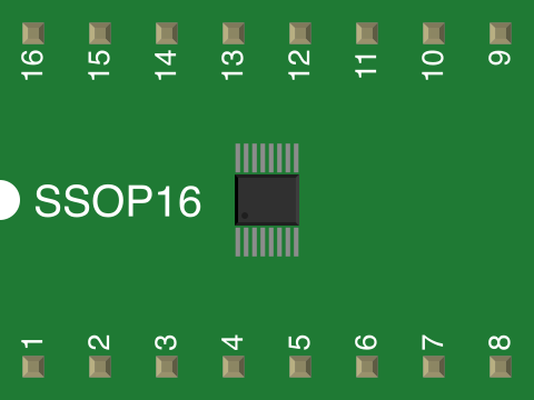
The SSOP16 (Shrink Small Outline Package) is a type of surface-mount package designed for integrated circuits. It is characterized by its compact size, thin profile, and 16 pins, making it ideal for applications where space is a critical factor. SSOP16 packages are widely used in modern electronics due to their ability to save board space while maintaining reliable electrical connections.
Explore Projects Built with SSOP16
 Open Project in Cirkit Designer
 Open Project in Cirkit Designer
 Open Project in Cirkit Designer
 Open Project in Cirkit Designer
Explore Projects Built with SSOP16
Open Project in Cirkit DesignerOpen Project in Cirkit DesignerOpen Project in Cirkit DesignerOpen Project in Cirkit DesignerCommon Applications and Use Cases
- Consumer electronics (e.g., smartphones, tablets, and wearables)
- Industrial control systems
- Automotive electronics
- Communication devices
- Signal processing and data conversion circuits
Technical Specifications
The SSOP16 package is designed to meet the needs of compact and high-density circuit designs. Below are the key technical details and pin configuration:
Key Technical Details
| Parameter | Value |
|---|---|
| Number of Pins | 16 |
| Package Type | Shrink Small Outline Package |
| Pin Pitch | 0.635 mm |
| Body Width | 3.9 mm |
| Body Length | 5.0 mm |
| Maximum Height | 1.75 mm |
| Mounting Type | Surface Mount Technology (SMT) |
| Thermal Resistance | Varies by IC, typically 100°C/W |
| Operating Temperature | -40°C to +125°C (typical) |
Pin Configuration and Descriptions
The pin configuration of an SSOP16 package depends on the specific integrated circuit housed within it. Below is a generic example of a pinout for an SSOP16 IC:
| Pin Number | Pin Name | Description |
|---|---|---|
| 1 | VCC | Power supply input |
| 2 | GND | Ground |
| 3 | IN1 | Input signal 1 |
| 4 | IN2 | Input signal 2 |
| 5 | OUT1 | Output signal 1 |
| 6 | OUT2 | Output signal 2 |
| 7 | CLK | Clock input |
| 8 | RESET | Reset signal |
| 9 | DATA | Data input/output |
| 10 | ENABLE | Enable signal |
| 11 | NC | No connection |
| 12 | NC | No connection |
| 13 | TEST | Test pin (optional) |
| 14 | VREF | Voltage reference input |
| 15 | OUT3 | Output signal 3 |
| 16 | OUT4 | Output signal 4 |
Note: The actual pinout may vary depending on the specific IC model. Always refer to the datasheet of the IC for accurate pin descriptions.
Usage Instructions
How to Use the SSOP16 in a Circuit
- PCB Design: Ensure your PCB layout includes a footprint for the SSOP16 package with a pin pitch of 0.635 mm. Use solder mask openings and pads that match the dimensions of the package.
- Soldering: Use surface-mount soldering techniques such as reflow soldering. Ensure proper alignment of the pins with the PCB pads.
- Power Supply: Connect the VCC and GND pins to the appropriate power supply and ground lines. Verify the voltage and current requirements of the IC housed in the SSOP16 package.
- Signal Connections: Connect the input and output pins to the corresponding circuit components. Use decoupling capacitors near the power pins to reduce noise.
- Testing: After assembly, test the circuit to ensure all connections are functioning as expected.
Important Considerations and Best Practices
- Thermal Management: Ensure adequate heat dissipation, especially for high-power ICs. Use thermal vias or heat sinks if necessary.
- ESD Protection: Handle the SSOP16 package with care to avoid electrostatic discharge (ESD) damage. Use ESD-safe tools and workstations.
- Soldering Temperature: Follow the recommended soldering temperature profile to avoid damaging the package or the IC.
- Pinout Verification: Always refer to the specific IC datasheet for the correct pinout and electrical characteristics.
Example: Using SSOP16 with Arduino UNO
If the SSOP16 package contains an IC such as a digital-to-analog converter (DAC), you can interface it with an Arduino UNO. Below is an example code snippet for interfacing a DAC IC in an SSOP16 package:
#include <Wire.h> // Include the Wire library for I2C communication

#define DAC_ADDRESS 0x60 // I2C address of the DAC IC

void setup() {
  Wire.begin(); // Initialize I2C communication
  Serial.begin(9600); // Initialize serial communication for debugging
  Serial.println("Initializing DAC...");
}

void loop() {
  // Send a value to the DAC
  Wire.beginTransmission(DAC_ADDRESS); // Start communication with DAC
  Wire.write(0x40); // Command to set DAC output
  Wire.write(128);  // Set output to mid-scale (example value)
  Wire.endTransmission(); // End communication

  Serial.println("DAC output set to mid-scale.");
  delay(1000); // Wait for 1 second before updating again
}
Note: Replace DAC_ADDRESS and commands with the appropriate values for your specific IC.
Troubleshooting and FAQs
Common Issues
- Incorrect Pin Connections: Misaligned or incorrect pin connections can cause the IC to malfunction.
- Solution: Double-check the pinout and ensure proper alignment during soldering.
- Overheating: Excessive heat during soldering or operation can damage the package.
- Solution: Use a proper soldering temperature profile and ensure adequate thermal management.
- No Output Signal: The IC may not function if the power supply or input signals are incorrect.
- Solution: Verify the power supply voltage, input signals, and enable pins.
FAQs
Q: Can I hand-solder an SSOP16 package?
A: Yes, but it requires precision and the use of fine-tipped soldering tools. Reflow soldering is recommended for better results.
Q: How do I clean flux residue after soldering?
A: Use isopropyl alcohol and a soft brush to clean the PCB. Ensure the board is completely dry before powering it.
Q: What should I do if the IC in the SSOP16 package overheats?
A: Check for proper power supply levels, ensure adequate heat dissipation, and verify that the IC is not being overdriven.
Q: Can I use an SSOP16 IC on a breadboard?
A: Not directly. You will need an SSOP16-to-DIP adapter to use it with a breadboard.