How to Use Traffic Light Module: Examples, Pinouts, and Specs
Introduction
The Traffic Light Module is an electronic component designed to simulate the operation of a standard traffic light. It typically features three LEDs: red, yellow, and green, which represent stop, caution, and go signals, respectively. This module is widely used in educational projects, robotics, and traffic control system prototypes. It is an excellent tool for learning about timing, sequencing, and state management in circuits.
Explore Projects Built with Traffic Light Module
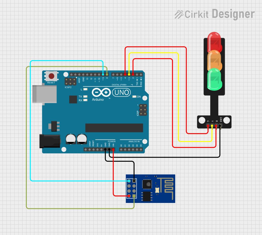
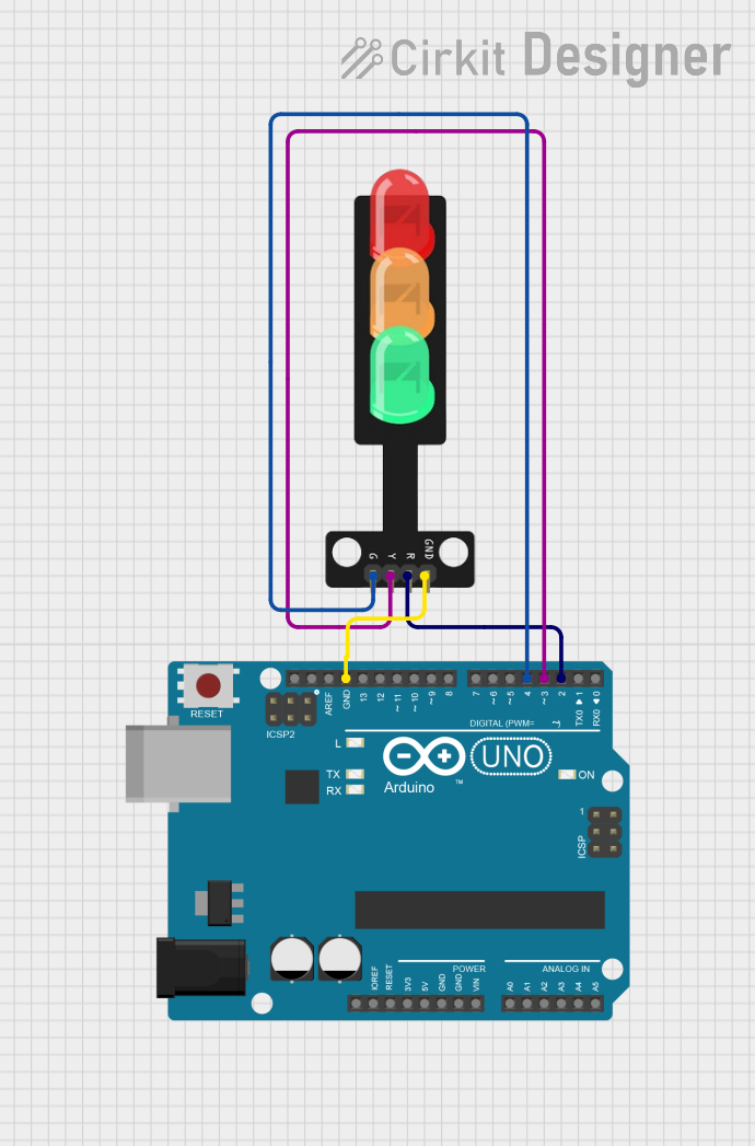
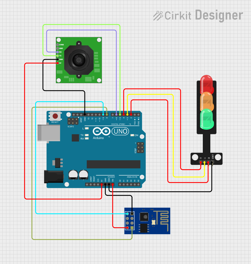
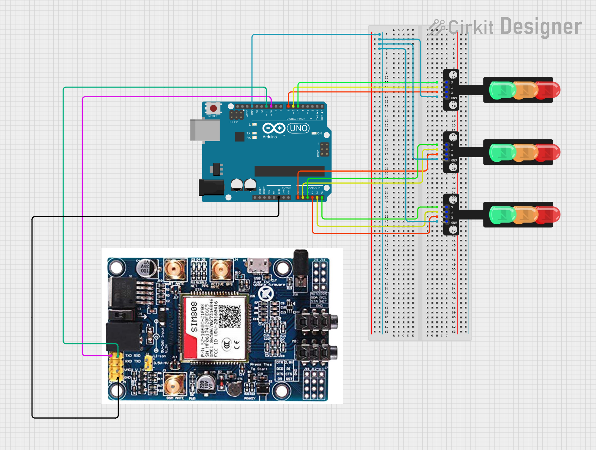
Explore Projects Built with Traffic Light Module
Common Applications and Use Cases
- Educational projects to teach basic electronics and programming concepts.
- Prototyping traffic control systems for smart cities.
- Robotics projects to manage traffic flow in autonomous systems.
- Visual indicators in circuits to represent different states or modes.
Technical Specifications
The Traffic Light Module is a simple yet versatile component. Below are its key technical details:
Key Technical Details
- Operating Voltage: 3.3V to 5V DC
- Current Consumption: ~20mA per LED
- LED Colors: Red, Yellow, Green
- Control Method: Digital signal (HIGH/LOW) for each LED
- Dimensions: Typically 30mm x 20mm (varies by manufacturer)
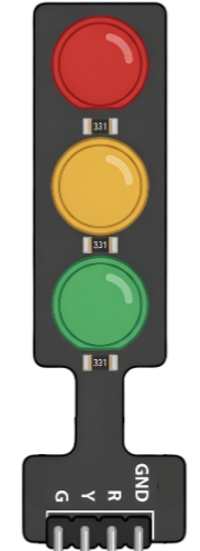
Pin Configuration and Descriptions
The module typically has 4 pins, as described in the table below:
| Pin | Name | Description |
|---|---|---|
| 1 | GND | Ground pin. Connect to the ground of the power supply or microcontroller. |
| 2 | VCC | Power pin. Connect to a 3.3V or 5V power source. |
| 3 | Green LED | Control pin for the green LED. Set HIGH to turn on, LOW to turn off. |
| 4 | Yellow LED | Control pin for the yellow LED. Set HIGH to turn on, LOW to turn off. |
| 5 | Red LED | Control pin for the red LED. Set HIGH to turn on, LOW to turn off. |
Usage Instructions
How to Use the Traffic Light Module in a Circuit
- Power the Module: Connect the
VCCpin to a 3.3V or 5V power source and theGNDpin to the ground. - Control the LEDs: Use a microcontroller (e.g., Arduino UNO) to send digital HIGH/LOW signals to the
Green LED,Yellow LED, andRed LEDpins to control the LEDs. - Resistors (Optional): If the module does not include built-in resistors, add appropriate resistors (e.g., 220Ω) in series with each LED to limit current and prevent damage.
Important Considerations and Best Practices
- Voltage Compatibility: Ensure the module's operating voltage matches your power supply or microcontroller.
- Current Limiting: Verify whether the module includes built-in resistors. If not, add external resistors to protect the LEDs.
- Timing Logic: When simulating a traffic light, use appropriate delays to mimic real-world timing (e.g., green for 10 seconds, yellow for 3 seconds, red for 10 seconds).
Example Code for Arduino UNO
Below is an example Arduino sketch to control the Traffic Light Module:
// Pin assignments for the Traffic Light Module
const int redPin = 5;    // Red LED connected to digital pin 5
const int yellowPin = 6; // Yellow LED connected to digital pin 6
const int greenPin = 7;  // Green LED connected to digital pin 7

void setup() {
  // Set the LED pins as outputs
  pinMode(redPin, OUTPUT);
  pinMode(yellowPin, OUTPUT);
  pinMode(greenPin, OUTPUT);
}

void loop() {
  // Turn on the green LED for 10 seconds
  digitalWrite(greenPin, HIGH);
  digitalWrite(yellowPin, LOW);
  digitalWrite(redPin, LOW);
  delay(10000); // Wait for 10 seconds

  // Turn on the yellow LED for 3 seconds
  digitalWrite(greenPin, LOW);
  digitalWrite(yellowPin, HIGH);
  digitalWrite(redPin, LOW);
  delay(3000); // Wait for 3 seconds

  // Turn on the red LED for 10 seconds
  digitalWrite(greenPin, LOW);
  digitalWrite(yellowPin, LOW);
  digitalWrite(redPin, HIGH);
  delay(10000); // Wait for 10 seconds
}
Troubleshooting and FAQs
Common Issues and Solutions
LEDs Not Lighting Up:
- Cause: Incorrect wiring or insufficient power supply.
- Solution: Double-check the connections and ensure the power supply matches the module's voltage requirements.
LEDs Too Dim:
- Cause: Excessive resistance in the circuit.
- Solution: Verify the resistor values. Use 220Ω resistors if external resistors are required.
Module Overheating:
- Cause: Excessive current through the LEDs.
- Solution: Ensure current-limiting resistors are in place if the module lacks built-in resistors.
Incorrect LED Behavior:
- Cause: Faulty code or incorrect pin assignments.
- Solution: Check the Arduino sketch for errors and confirm the pin assignments match your circuit.
FAQs
Q: Can I use the Traffic Light Module with a 3.3V microcontroller?
A: Yes, the module is compatible with both 3.3V and 5V systems. Ensure the power supply matches the microcontroller's voltage.
Q: Does the module include built-in resistors?
A: Some modules include built-in resistors, while others do not. Check the manufacturer's datasheet or documentation to confirm.
Q: Can I control the module without a microcontroller?
A: Yes, you can use simple switches or a 555 timer circuit to control the LEDs, but a microcontroller provides more flexibility and precision.
Q: How do I extend the timing for each LED?
A: Modify the delay() values in the Arduino sketch to adjust the duration for each LED state. For example, increase delay(10000) to delay(15000) for a 15-second green light.
This documentation provides all the necessary details to get started with the Traffic Light Module, making it an ideal choice for beginners and advanced users alike.