Cirkit Designer
Your all-in-one circuit design IDE
Home /
Component Documentation
How to Use TM1638 display & switch: Examples, Pinouts, and Specs
Introduction
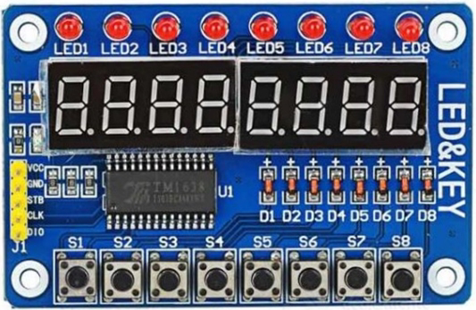
The TM1638 is an integrated circuit designed by TM that combines an LED display driver and a key scan interface. This versatile component is widely used in microcontroller projects to control 7-segment displays and read input from a matrix of switches. Its ability to handle both display and input functions makes it an excellent choice for creating user interfaces in embedded systems.
Explore Projects Built with TM1638 display & switch
Arduino Nano 33 BLE Battery-Powered Display Interface

This circuit features a Nano 33 BLE microcontroller interfaced with a TM1637 4-digit 7-segment display for information output, powered by a 3.7V battery managed by a TP4056 charging module. The microcontroller communicates with the display to present data, while the TP4056 ensures the battery is charged safely and provides power to the system.
Arduino Nano and TM1637 Real-Time Clock Display
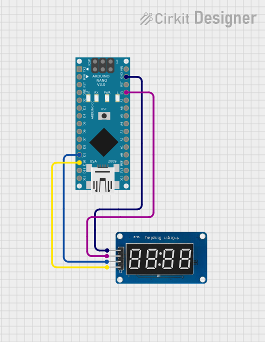
This circuit uses an Arduino Nano to control a TM1637 4-digit 7-segment display module, displaying the current time. The Arduino reads the time from an RTC (Real-Time Clock) module and updates the display every second.
STM32F103C8T6-Based Spectral Sensor with ST7735S Display and Pushbutton Control

This circuit features an STM32F103C8T6 microcontroller interfaced with a China ST7735S 160x128 display and two spectral sensors (Adafruit AS7262 and AS7261). It also includes two pushbuttons for user input, with the microcontroller managing the display and sensor data processing.
Arduino UNO Controlled TM1637 Display and SG90 Servo Motor Interface
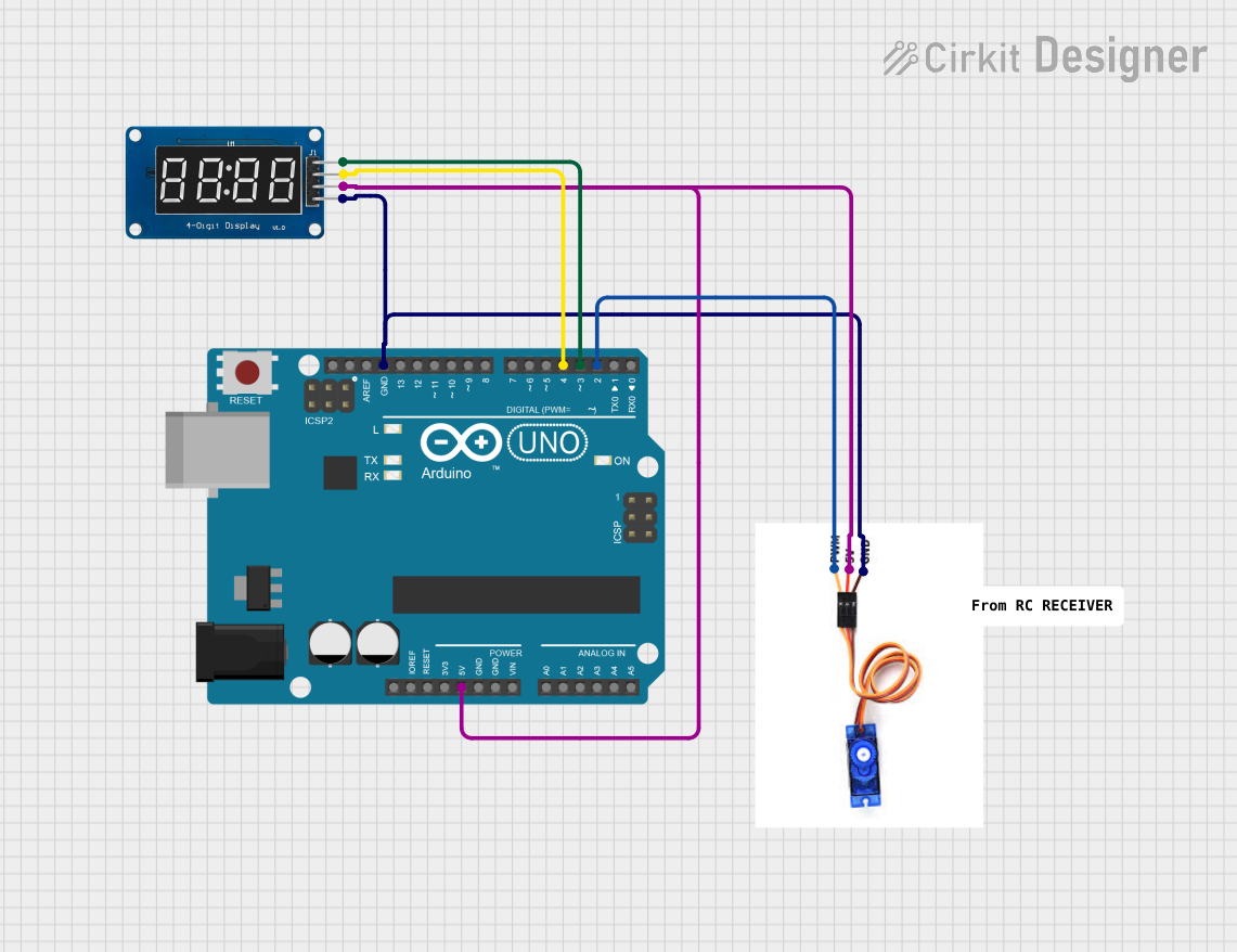
This circuit features an Arduino UNO microcontroller connected to a TM1637 display module and an SG90 servo motor. The Arduino provides power to both the display and the servo motor, and it controls the display via digital pins D4 (DIO) and D3 (CLK), and the servo motor via pin D2 (PWM). The primary function of this circuit is likely to display information on the TM1637 module and to control the position or motion of the servo motor based on some programmed logic within the Arduino.
Explore Projects Built with TM1638 display & switch
Arduino Nano 33 BLE Battery-Powered Display Interface
This circuit features a Nano 33 BLE microcontroller interfaced with a TM1637 4-digit 7-segment display for information output, powered by a 3.7V battery managed by a TP4056 charging module. The microcontroller communicates with the display to present data, while the TP4056 ensures the battery is charged safely and provides power to the system.
Arduino Nano and TM1637 Real-Time Clock Display
This circuit uses an Arduino Nano to control a TM1637 4-digit 7-segment display module, displaying the current time. The Arduino reads the time from an RTC (Real-Time Clock) module and updates the display every second.
STM32F103C8T6-Based Spectral Sensor with ST7735S Display and Pushbutton Control
This circuit features an STM32F103C8T6 microcontroller interfaced with a China ST7735S 160x128 display and two spectral sensors (Adafruit AS7262 and AS7261). It also includes two pushbuttons for user input, with the microcontroller managing the display and sensor data processing.
Arduino UNO Controlled TM1637 Display and SG90 Servo Motor Interface
This circuit features an Arduino UNO microcontroller connected to a TM1637 display module and an SG90 servo motor. The Arduino provides power to both the display and the servo motor, and it controls the display via digital pins D4 (DIO) and D3 (CLK), and the servo motor via pin D2 (PWM). The primary function of this circuit is likely to display information on the TM1637 module and to control the position or motion of the servo motor based on some programmed logic within the Arduino.
Common Applications and Use Cases
- Digital clocks and timers
- Scoreboards
- User interfaces for embedded systems
- Home automation control panels
- Educational projects and prototyping
Technical Specifications
Key Technical Details
| Parameter | Value |
|---|---|
| Operating Voltage | 5V |
| Operating Current | 80mA (typical) |
| Display Type | 8-digit 7-segment LED |
| Key Scan | 8x3 matrix |
| Communication | Serial (3-wire interface) |
| Package Type | SOP-28 |
Pin Configuration and Descriptions
| Pin No. | Pin Name | Description |
|---|---|---|
| 1 | VDD | Power Supply (5V) |
| 2 | GND | Ground |
| 3 | DIO | Data Input/Output |
| 4 | CLK | Clock Input |
| 5 | STB | Strobe (Chip Select) |
| 6-13 | SEG1-SEG8 | Segment Outputs for 7-segment displays |
| 14-21 | GRID1-GRID8 | Grid Outputs for 7-segment displays |
| 22-28 | K1-K8 | Key Scan Inputs |
Usage Instructions
How to Use the Component in a Circuit
- Power Supply: Connect the VDD pin to a 5V power supply and the GND pin to ground.
- Data Communication: Connect the DIO, CLK, and STB pins to the corresponding pins on your microcontroller.
- Display Connection: Connect the SEG1-SEG8 and GRID1-GRID8 pins to the 7-segment displays.
- Key Scan: Connect the K1-K8 pins to the matrix of switches.
Important Considerations and Best Practices
- Power Supply: Ensure a stable 5V power supply to avoid display flickering and erratic key inputs.
- Decoupling Capacitors: Place a 0.1µF capacitor close to the VDD and GND pins to filter out noise.
- Pull-up Resistors: Use pull-up resistors on the key scan lines to ensure reliable key detection.
- Serial Communication: Use appropriate timing for the serial communication to avoid data corruption.
Example Circuit Diagram

Arduino UNO Example Code
#include <TM1638.h>

// Define the pins for the TM1638 module
#define DIO_PIN 2
#define CLK_PIN 3
#define STB_PIN 4

// Create an instance of the TM1638 class
TM1638 module(DIO_PIN, CLK_PIN, STB_PIN);

void setup() {
  // Initialize the module
  module.setupDisplay(true, 7); // Turn on display, set brightness to max (7)
}

void loop() {
  // Display a number on the 7-segment display
  module.setDisplayToDecNumber(12345678, 0x00, true);

  // Read the key inputs
  uint8_t keys = module.getButtons();

  // Check if any key is pressed
  if (keys != 0) {
    // Display the key value on the first digit
    module.setDisplayDigit(keys, 0, false);
  }

  delay(100); // Small delay to debounce keys
}
Troubleshooting and FAQs
Common Issues Users Might Face
- Display Flickering: This can be caused by an unstable power supply or insufficient current. Ensure a stable 5V supply and check the current rating.
- No Display Output: Verify the connections, especially the DIO, CLK, and STB pins. Ensure the microcontroller is correctly programmed.
- Erratic Key Inputs: This can be due to noise or lack of pull-up resistors. Add pull-up resistors to the key scan lines and use decoupling capacitors.
Solutions and Tips for Troubleshooting
- Check Connections: Ensure all connections are secure and correctly mapped.
- Use a Multimeter: Measure the voltage levels at the VDD and GND pins to ensure proper power supply.
- Verify Code: Double-check the code for any logical errors or incorrect pin assignments.
- Consult Datasheet: Refer to the TM1638 datasheet for detailed information and advanced configurations.
Conclusion
The TM1638 display and switch module is a powerful and versatile component for creating interactive displays and user interfaces in microcontroller projects. By following the guidelines and best practices outlined in this documentation, users can effectively integrate the TM1638 into their projects and troubleshoot common issues with ease.