How to Use TB6612FNG Quad DC Motor Driver Shield: Examples, Pinouts, and Specs
Introduction
The TB6612FNG Quad DC Motor Driver Shield (Manufacturer Part ID: DRI0039) by DFRobot is a versatile motor driver shield designed to control up to four DC motors. It features PWM speed control and direction control, making it an excellent choice for robotics, automation, and other motor-driven projects. This shield is based on the Toshiba TB6612FNG motor driver IC, which provides efficient and reliable motor control with minimal heat generation.
Explore Projects Built with TB6612FNG Quad DC Motor Driver Shield


Explore Projects Built with TB6612FNG Quad DC Motor Driver Shield
Common Applications and Use Cases
- Robotics projects requiring precise motor control
- Automated vehicles and drones
- Conveyor belt systems
- DIY motorized projects
- Educational kits for learning motor control and robotics
Technical Specifications
The following are the key technical details of the TB6612FNG Quad DC Motor Driver Shield:
General Specifications
- Input Voltage (Logic): 2.7V to 5.5V
- Motor Supply Voltage (VM): 4.5V to 13.5V
- Output Current (Per Channel): 1.2A (continuous), 3.2A (peak)
- PWM Frequency: Up to 100 kHz
- Control Interface: Arduino-compatible pinout
- Dimensions: 68mm x 53mm x 12mm
- Weight: 28g
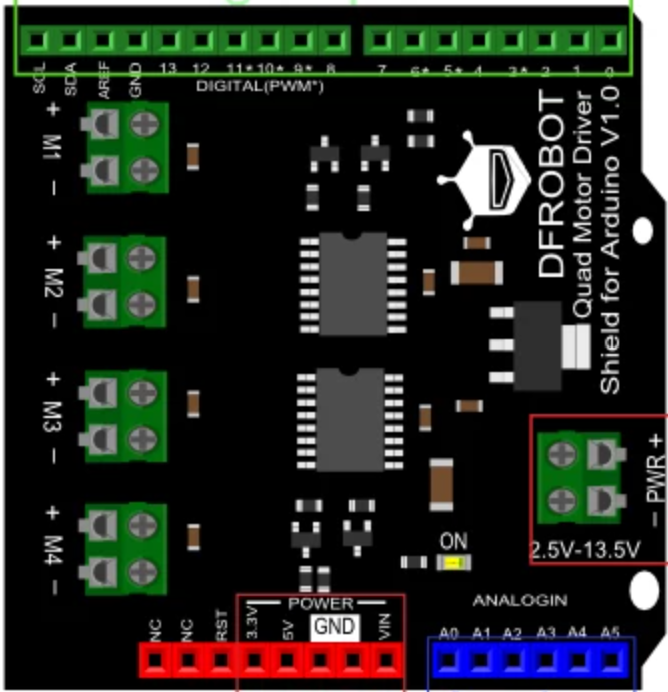
Pin Configuration and Descriptions
The shield uses an Arduino-compatible pinout for easy integration. Below is the pin configuration:
| Pin | Description |
|---|---|
VM |
Motor power supply (4.5V to 13.5V). |
GND |
Ground connection. |
VCC |
Logic power supply (2.7V to 5.5V). |
A1, A2 |
Motor A control pins (direction control). |
B1, B2 |
Motor B control pins (direction control). |
C1, C2 |
Motor C control pins (direction control). |
D1, D2 |
Motor D control pins (direction control). |
PWMA |
PWM input for Motor A speed control. |
PWMB |
PWM input for Motor B speed control. |
PWMC |
PWM input for Motor C speed control. |
PWMD |
PWM input for Motor D speed control. |
STBY |
Standby pin (active low). |
EN |
Enable pin for the shield. |
Usage Instructions
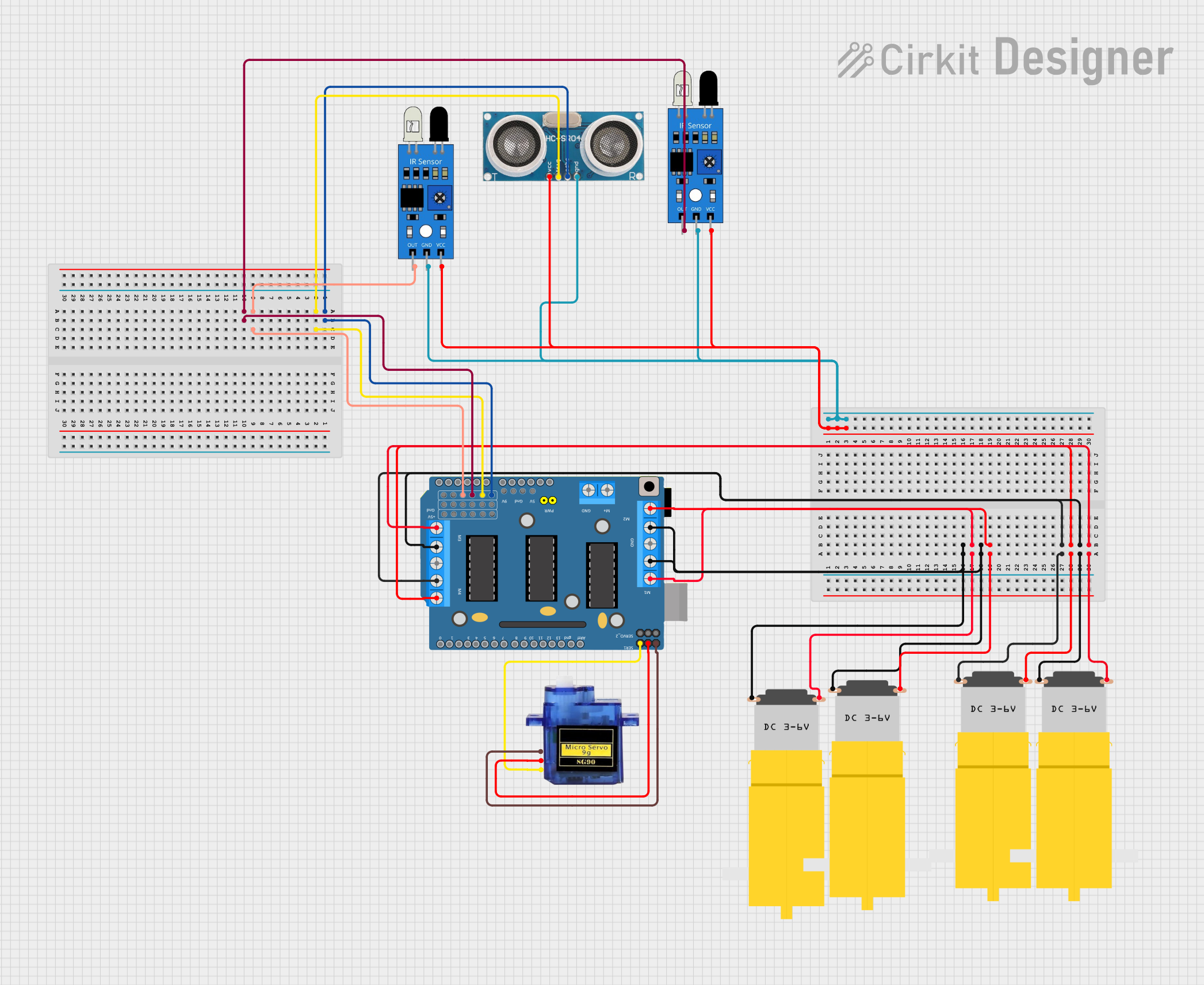
How to Use the Component in a Circuit
Power Supply:
- Connect the motor power supply (VM) to a voltage source between 4.5V and 13.5V.
- Connect the logic power supply (VCC) to a 5V source (e.g., from the Arduino UNO).
- Ensure the GND pin is connected to the common ground of the circuit.
Motor Connections:
- Connect the terminals of each DC motor to the corresponding motor output pins (e.g., Motor A to
A1andA2). - Use the PWM pins (
PWMA,PWMB, etc.) to control the speed of each motor.
- Connect the terminals of each DC motor to the corresponding motor output pins (e.g., Motor A to
Control Signals:
- Use the direction control pins (
A1,A2, etc.) to set the rotation direction of each motor. - Set the
STBYpin to HIGH to enable the shield.
- Use the direction control pins (
Arduino Integration:
- Mount the shield directly onto an Arduino UNO or compatible board.
- Use the Arduino's digital pins to send PWM and direction control signals.
Important Considerations and Best Practices
- Ensure the motor power supply voltage matches the requirements of your motors.
- Avoid exceeding the maximum continuous current rating of 1.2A per channel.
- Use heat sinks or active cooling if operating near the peak current limit for extended periods.
- Always set the
STBYpin to HIGH before operating the motors. - Use appropriate decoupling capacitors to minimize noise in the circuit.
Example Arduino Code
Below is an example Arduino sketch to control two DC motors using the TB6612FNG Quad DC Motor Driver Shield:
// Example code to control two DC motors with the TB6612FNG Quad Motor Driver Shield

// Define motor control pins
#define A1 2       // Motor A direction pin 1
#define A2 3       // Motor A direction pin 2
#define PWMA 5     // Motor A PWM pin
#define B1 4       // Motor B direction pin 1
#define B2 7       // Motor B direction pin 2
#define PWMB 6     // Motor B PWM pin
#define STBY 8     // Standby pin

void setup() {
  // Set motor control pins as outputs
  pinMode(A1, OUTPUT);
  pinMode(A2, OUTPUT);
  pinMode(PWMA, OUTPUT);
  pinMode(B1, OUTPUT);
  pinMode(B2, OUTPUT);
  pinMode(PWMB, OUTPUT);
  pinMode(STBY, OUTPUT);

  // Enable the motor driver shield
  digitalWrite(STBY, HIGH);
}

void loop() {
  // Motor A: Forward at 50% speed
  digitalWrite(A1, HIGH);
  digitalWrite(A2, LOW);
  analogWrite(PWMA, 128); // 50% duty cycle (0-255)

  // Motor B: Reverse at 75% speed
  digitalWrite(B1, LOW);
  digitalWrite(B2, HIGH);
  analogWrite(PWMB, 192); // 75% duty cycle (0-255)

  delay(2000); // Run motors for 2 seconds

  // Stop both motors
  analogWrite(PWMA, 0);
  analogWrite(PWMB, 0);

  delay(2000); // Wait for 2 seconds
}
Troubleshooting and FAQs
Common Issues and Solutions
Motors Not Running:
- Ensure the
STBYpin is set to HIGH. - Verify that the motor power supply (VM) is connected and within the specified range.
- Check the wiring of the motor terminals and control pins.
- Ensure the
Erratic Motor Behavior:
- Check for loose connections or poor solder joints.
- Add decoupling capacitors near the motor terminals to reduce electrical noise.
Overheating:
- Ensure the current draw of the motors does not exceed the shield's maximum rating.
- Use heat sinks or active cooling if necessary.
Arduino Not Responding:
- Verify that the shield is properly seated on the Arduino.
- Check for pin conflicts with other shields or components.
FAQs
Q: Can I use this shield with stepper motors?
A: No, this shield is designed for DC motors only. For stepper motors, consider using a dedicated stepper motor driver.
Q: What happens if I exceed the current rating?
A: Exceeding the current rating may cause the shield to overheat or shut down. Prolonged overcurrent conditions can damage the shield.
Q: Can I control all four motors simultaneously?
A: Yes, the shield supports independent control of up to four DC motors.
Q: Is this shield compatible with Arduino Mega?
A: Yes, the shield is compatible with Arduino Mega, but ensure the pin mappings are correct.
This concludes the documentation for the TB6612FNG Quad DC Motor Driver Shield.