How to Use Electric Linear Actuator Controller: Examples, Pinouts, and Specs
Introduction
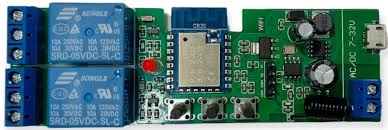
The Electric Linear Actuator Controller (Manufacturer: Tuya, Part ID: AllbeAI) is a versatile device designed to regulate the operation of electric linear actuators. It enables precise control of movement, speed, and position, making it an essential component in applications requiring linear motion. This controller is widely used in robotics, home automation, industrial machinery, and medical devices, where accurate and reliable actuator control is critical.
Explore Projects Built with Electric Linear Actuator Controller
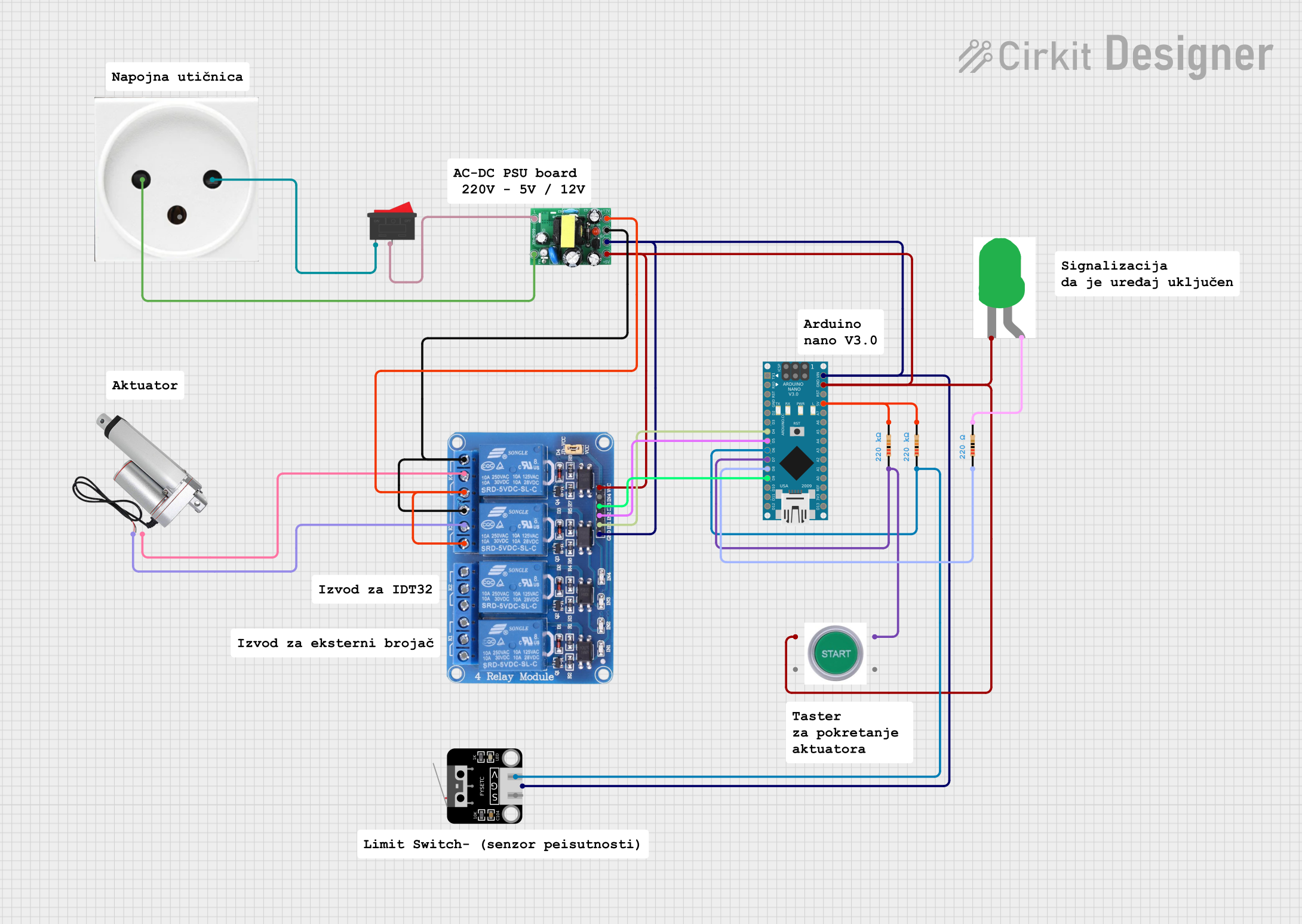
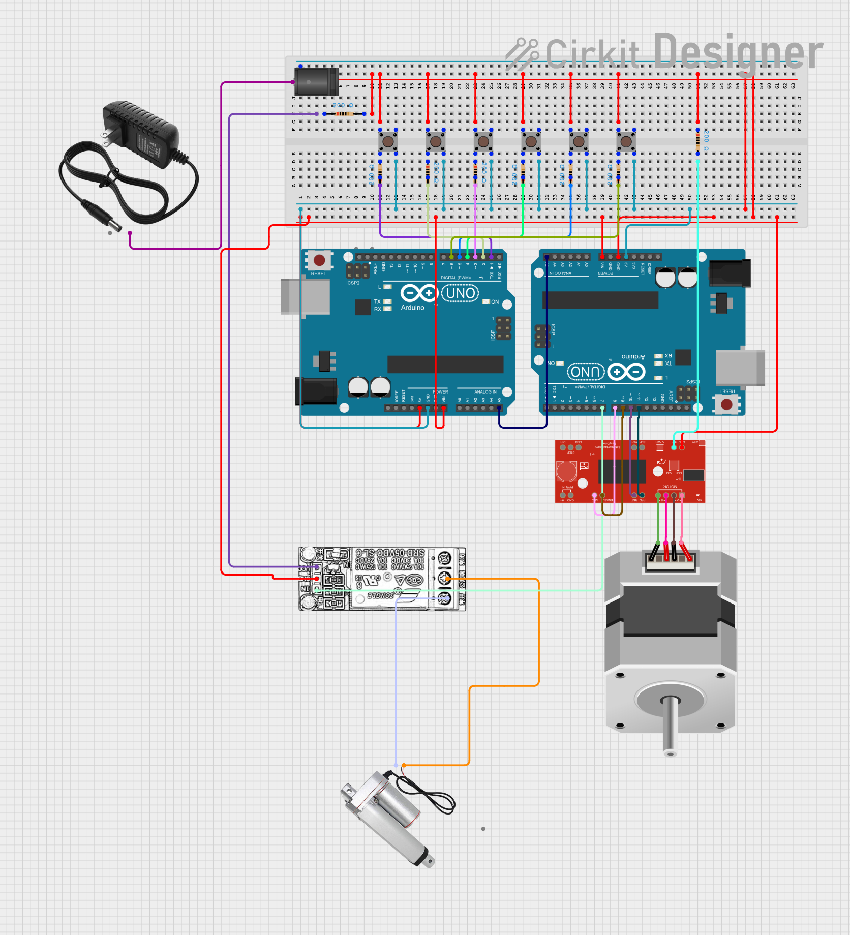
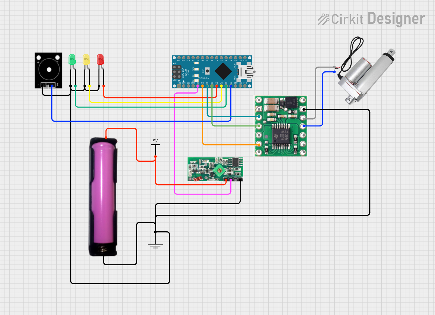
Explore Projects Built with Electric Linear Actuator Controller
Common Applications
- Robotics: For controlling robotic arms and grippers.
- Home Automation: Adjusting furniture, such as recliners or standing desks.
- Industrial Machinery: Managing conveyor belts, presses, and other automated systems.
- Medical Devices: Operating hospital beds and patient lifts.
- Agriculture: Automating greenhouse vents or irrigation systems.
Technical Specifications
Key Technical Details
| Parameter | Value |
|---|---|
| Input Voltage | 12V DC / 24V DC |
| Maximum Current | 10A |
| Control Signal | PWM (Pulse Width Modulation) |
| Position Feedback | Potentiometer or Hall Effect Sensor |
| Operating Temperature | -10°C to 50°C |
| Communication Protocol | UART, RS485, or Bluetooth (optional) |
| Dimensions | 100mm x 60mm x 25mm |
| Weight | 150g |
Pin Configuration and Descriptions
| Pin Number | Pin Name | Description |
|---|---|---|
| 1 | VCC | Power input (12V or 24V DC) |
| 2 | GND | Ground connection |
| 3 | PWM_IN | PWM signal input for speed and direction control |
| 4 | FEEDBACK | Position feedback input from the actuator (e.g., potentiometer or Hall sensor) |
| 5 | DIR | Direction control input (HIGH for forward, LOW for reverse) |
| 6 | ENABLE | Enable/disable the actuator (HIGH to enable, LOW to disable) |
| 7 | UART_TX | UART transmit pin for communication (optional) |
| 8 | UART_RX | UART receive pin for communication (optional) |
Usage Instructions
How to Use the Component in a Circuit
- Power Connection: Connect the VCC and GND pins to a 12V or 24V DC power supply, depending on the actuator's requirements.
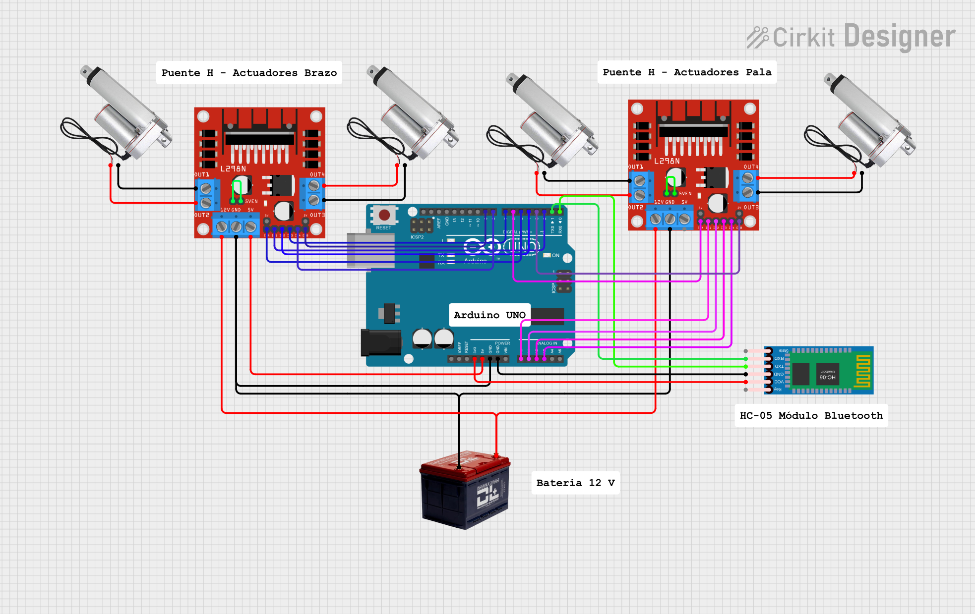
- Control Signal: Use a microcontroller (e.g., Arduino UNO) to generate a PWM signal and connect it to the PWM_IN pin.
- Direction Control: Use a digital output pin from the microcontroller to control the DIR pin for forward or reverse motion.
- Position Feedback: Connect the actuator's feedback signal (potentiometer or Hall sensor) to the FEEDBACK pin for precise position monitoring.
- Enable/Disable: Use a digital output pin to toggle the ENABLE pin for activating or deactivating the actuator.
Important Considerations and Best Practices
- Ensure the power supply voltage matches the actuator's requirements to avoid damage.
- Use appropriate pull-up or pull-down resistors for the DIR and ENABLE pins if required.
- If using UART communication, ensure the baud rate matches the controller's specifications.
- Avoid exceeding the maximum current rating (10A) to prevent overheating or damage.
- For safety, include a fuse or circuit breaker in the power supply line.
Example Code for Arduino UNO
Below is an example code snippet to control the Electric Linear Actuator Controller using an Arduino UNO:
// Define pin connections
const int pwmPin = 9;       // PWM signal pin
const int dirPin = 8;       // Direction control pin
const int enablePin = 7;    // Enable pin

void setup() {
  // Set pin modes
  pinMode(pwmPin, OUTPUT);
  pinMode(dirPin, OUTPUT);
  pinMode(enablePin, OUTPUT);

  // Initialize actuator
  digitalWrite(enablePin, HIGH);  // Enable the actuator
  digitalWrite(dirPin, HIGH);     // Set direction to forward
}

void loop() {
  // Move actuator forward at 50% speed
  analogWrite(pwmPin, 128);  // PWM value (0-255, 128 = 50% duty cycle)
  delay(2000);               // Move for 2 seconds

  // Change direction to reverse
  digitalWrite(dirPin, LOW); // Set direction to reverse
  delay(1000);               // Wait for 1 second

  // Move actuator reverse at 75% speed
  analogWrite(pwmPin, 192);  // PWM value (192 = 75% duty cycle)
  delay(2000);               // Move for 2 seconds

  // Stop the actuator
  analogWrite(pwmPin, 0);    // Set PWM to 0 (stop)
  delay(1000);               // Wait for 1 second
}
Troubleshooting and FAQs
Common Issues and Solutions
Actuator Not Moving:
- Cause: ENABLE pin is LOW.
- Solution: Ensure the ENABLE pin is set to HIGH.
Incorrect Direction:
- Cause: DIR pin is not set correctly.
- Solution: Verify the DIR pin logic (HIGH for forward, LOW for reverse).
No Position Feedback:
- Cause: Feedback signal not connected or incompatible.
- Solution: Check the actuator's feedback type (potentiometer or Hall sensor) and ensure proper wiring.
Overheating:
- Cause: Exceeding the maximum current rating.
- Solution: Use a power supply with current limiting or add a fuse.
Communication Failure (UART):
- Cause: Incorrect baud rate or wiring.
- Solution: Verify the baud rate and ensure proper TX/RX connections.
FAQs
Can I use this controller with a 5V microcontroller? Yes, but you may need level shifters for the control signals to match the controller's voltage levels.
What type of actuators are compatible? This controller supports electric linear actuators with 12V or 24V DC input and position feedback.
Is Bluetooth communication supported? Bluetooth is optional and depends on the specific model of the controller.
Can I control multiple actuators with one controller? No, this controller is designed to operate a single actuator. Use multiple controllers for multiple actuators.