How to Use GPS from Amazon: Examples, Pinouts, and Specs
Introduction
The Beffkkip GPS Module Receiver Dozer is a compact and efficient Global Positioning System (GPS) module designed to provide accurate location data by receiving signals from GPS satellites. This module is ideal for applications requiring real-time positioning, navigation, and tracking. Its small form factor and ease of integration make it suitable for use in a wide range of projects, including vehicle tracking systems, drones, robotics, and IoT devices.
Explore Projects Built with GPS from Amazon


Explore Projects Built with GPS from Amazon
Common Applications:
- Vehicle navigation and fleet management
- Personal tracking devices
- Drones and unmanned aerial vehicles (UAVs)
- Geographic surveying and mapping
- IoT-based location-aware systems
Technical Specifications
Below are the key technical details of the Beffkkip GPS Module Receiver Dozer:
| Parameter | Specification |
|---|---|
| Manufacturer | Beffkkip |
| Part ID | GPS Module Receiver Dozer |
| Input Voltage | 3.3V to 5.0V |
| Operating Current | 20mA (typical) |
| Communication Interface | UART (TTL level) |
| Baud Rate | 9600 bps (default, configurable) |
| Positioning Accuracy | 2.5 meters CEP (Circular Error Probable) |
| Update Rate | 1 Hz (default), configurable up to 10 Hz |
| Operating Temperature | -40°C to +85°C |
| Dimensions | 25mm x 25mm x 8mm |
| Antenna | External active antenna (included) |
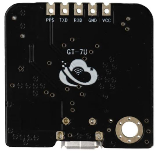
Pin Configuration and Descriptions
The GPS module has a simple pinout for easy integration into your projects. Below is the pin configuration:
| Pin | Name | Description |
|---|---|---|
| 1 | VCC | Power supply input (3.3V to 5.0V) |
| 2 | GND | Ground connection |
| 3 | TX | UART Transmit pin (sends GPS data to the host) |
| 4 | RX | UART Receive pin (receives commands from the host) |
| 5 | PPS | Pulse Per Second output for precise timing (optional) |
Usage Instructions
How to Use the GPS Module in a Circuit
- Power the Module: Connect the
VCCpin to a 3.3V or 5.0V power source and theGNDpin to ground. - Connect UART Pins:
- Connect the
TXpin of the GPS module to the RX pin of your microcontroller (e.g., Arduino UNO). - Connect the
RXpin of the GPS module to the TX pin of your microcontroller.
- Connect the
- Antenna Placement: Attach the included external active antenna to the module. Ensure the antenna has a clear view of the sky for optimal satellite reception.
- Configure Baud Rate (if needed): The default baud rate is 9600 bps. If required, you can configure the baud rate using specific commands sent via the UART interface.
- Read GPS Data: The module outputs NMEA sentences (e.g., GPGGA, GPRMC) containing location, time, and other data. Parse these sentences in your microcontroller or software to extract the required information.
Example: Connecting to an Arduino UNO
Below is an example of how to use the GPS module with an Arduino UNO to read and display GPS data:
Circuit Diagram:
- Connect
VCCto the 5V pin on the Arduino. - Connect
GNDto the GND pin on the Arduino. - Connect
TXof the GPS module toD4on the Arduino (software serial RX). - Connect
RXof the GPS module toD3on the Arduino (software serial TX).
Arduino Code:
#include <SoftwareSerial.h>

// Define software serial pins for GPS communication
SoftwareSerial gpsSerial(4, 3); // RX = D4, TX = D3

void setup() {
  Serial.begin(9600); // Initialize serial monitor
  gpsSerial.begin(9600); // Initialize GPS module communication

  Serial.println("GPS Module Receiver Dozer Test");
  Serial.println("Waiting for GPS data...");
}

void loop() {
  // Check if data is available from the GPS module
  while (gpsSerial.available()) {
    char c = gpsSerial.read(); // Read one character from GPS module
    Serial.print(c); // Print the character to the serial monitor

    // Note: The GPS module outputs NMEA sentences. You can parse these
    // sentences to extract specific data like latitude, longitude, etc.
  }
}
Important Considerations and Best Practices:
- Antenna Placement: Ensure the antenna is placed in an open area with minimal obstructions for better satellite reception.
- Power Supply: Use a stable power source to avoid interruptions in GPS data.
- UART Voltage Levels: Ensure the UART voltage levels of your microcontroller match the GPS module's requirements (TTL level).
- Cold Start vs. Warm Start: The module may take longer to acquire a GPS fix during a cold start (first power-up) compared to a warm start (subsequent power-ups).
Troubleshooting and FAQs
Common Issues and Solutions:
No GPS Fix (No Satellite Data Received):
- Ensure the antenna has a clear view of the sky.
- Check the power supply and connections.
- Wait for a few minutes, as the module may take time to acquire a fix during a cold start.
Garbage Data on Serial Monitor:
- Verify that the baud rate of the GPS module matches the baud rate in your code.
- Check the UART connections between the GPS module and the microcontroller.
Intermittent Data Loss:
- Ensure the power supply is stable and sufficient.
- Minimize electromagnetic interference near the module.
PPS Pin Not Working:
- The PPS pin is optional and may require additional configuration. Refer to the module's advanced settings if needed.
FAQs:
Q1: Can I use this GPS module indoors?
A1: GPS modules generally require a clear view of the sky for optimal performance. While it may work indoors near windows, the signal quality and accuracy will be reduced.
Q2: How do I increase the update rate?
A2: The default update rate is 1 Hz. You can send specific configuration commands via UART to increase the update rate up to 10 Hz. Refer to the module's advanced command set for details.
Q3: What is the purpose of the PPS pin?
A3: The PPS (Pulse Per Second) pin provides a precise timing signal that can be used for synchronization in time-sensitive applications.
Q4: Can I use this module with a 3.3V microcontroller?
A4: Yes, the module supports both 3.3V and 5.0V logic levels, making it compatible with a wide range of microcontrollers.
By following this documentation, you can effectively integrate the Beffkkip GPS Module Receiver Dozer into your projects and troubleshoot common issues with ease.