How to Use YH11060D: Examples, Pinouts, and Specs
Introduction
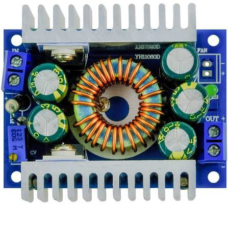
The YH11060D is a high-performance DC-DC buck converter designed for efficient voltage regulation in a wide range of electronic applications. This component is capable of stepping down a higher input voltage to a stable, adjustable lower output voltage, making it ideal for powering microcontrollers, sensors, and other low-voltage devices. Its compact design, high efficiency, and adjustable output voltage make it a versatile choice for embedded systems, IoT devices, and portable electronics.
Explore Projects Built with YH11060D

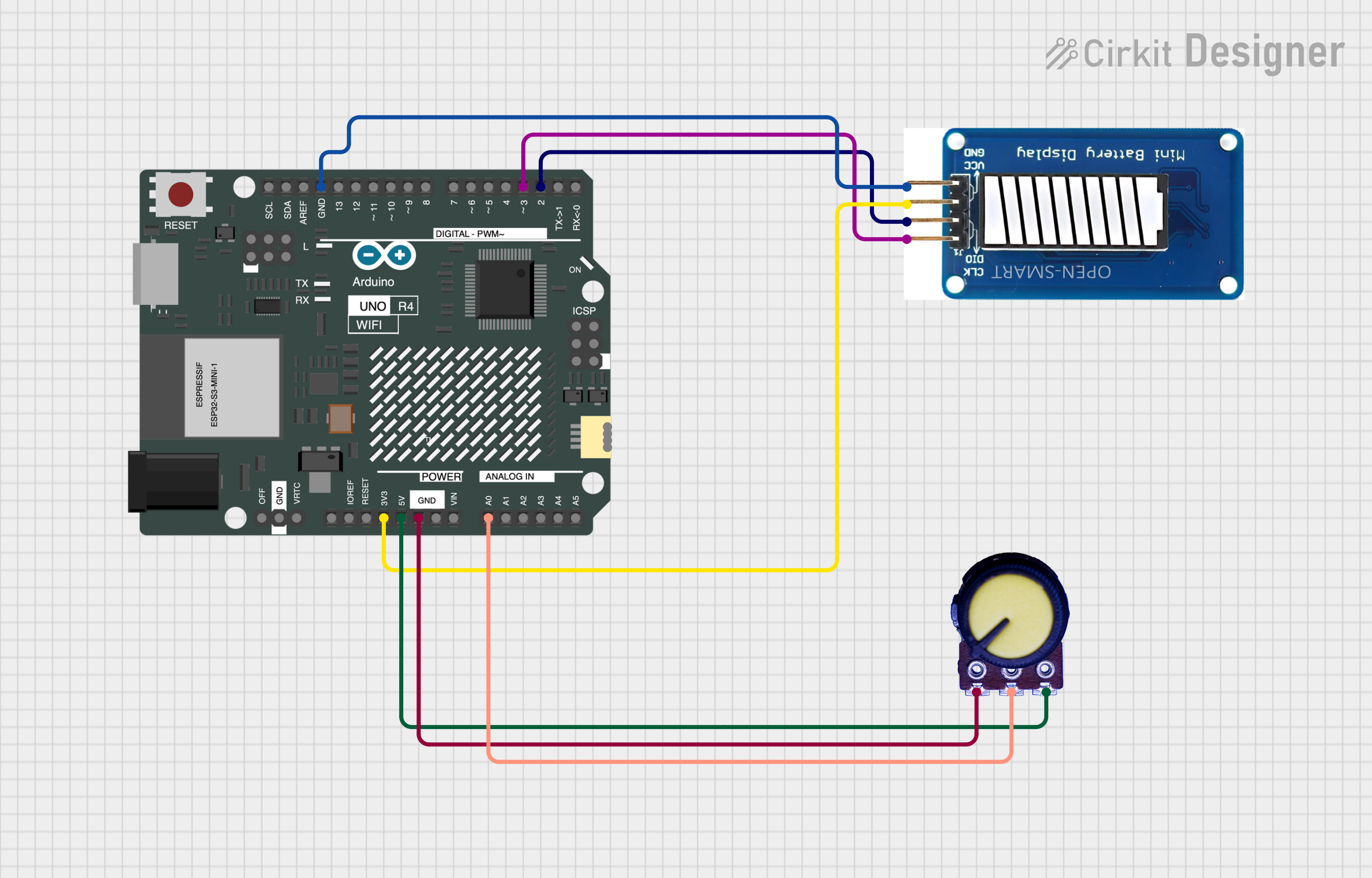
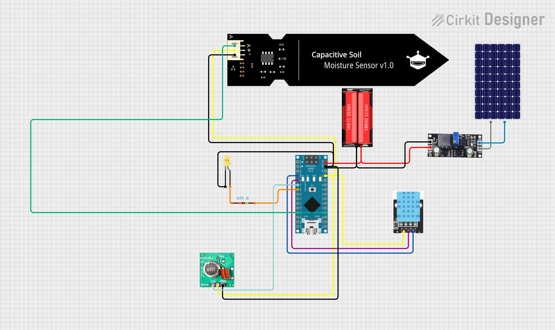
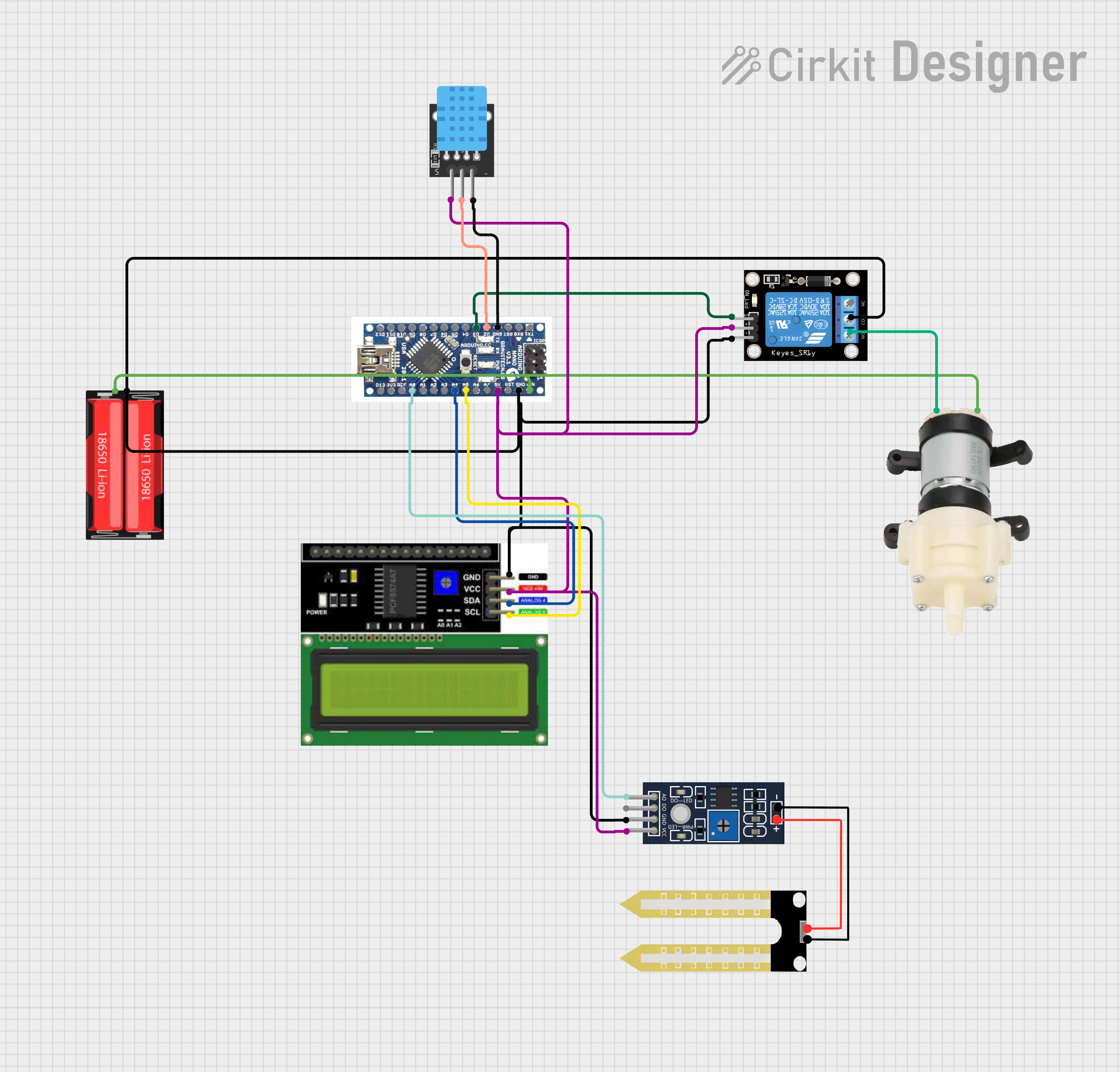
Explore Projects Built with YH11060D
Common Applications:
- Powering microcontrollers (e.g., Arduino, ESP32, Raspberry Pi Pico)
- Voltage regulation for sensors and modules
- Battery-powered devices
- Portable electronics
- IoT devices requiring efficient power management
Technical Specifications
The YH11060D offers robust performance with the following key specifications:
| Parameter | Value |
|---|---|
| Input Voltage Range | 4.5V to 28V |
| Output Voltage Range | 0.8V to 20V (adjustable) |
| Maximum Output Current | 3A |
| Efficiency | Up to 95% |
| Switching Frequency | 150 kHz |
| Operating Temperature | -40°C to +85°C |
| Dimensions | 22mm x 17mm x 4mm |
Pin Configuration and Descriptions
The YH11060D typically comes in a 6-pin configuration. Below is the pinout and description:
| Pin | Name | Description |
|---|---|---|
| 1 | VIN | Input voltage pin. Connect to the positive terminal of the input power source. |
| 2 | GND | Ground pin. Connect to the negative terminal of the input power source. |
| 3 | VOUT | Output voltage pin. Provides the regulated output voltage. |
| 4 | FB | Feedback pin. Used to set the output voltage via an external resistor divider. |
| 5 | EN | Enable pin. Pull high to enable the converter; pull low to disable it. |
| 6 | NC | No connection. Leave this pin unconnected. |
Usage Instructions
How to Use the YH11060D in a Circuit
- Input Voltage Connection: Connect the VIN pin to a DC power source within the input voltage range (4.5V to 28V). Ensure the power source can supply sufficient current for your application.
- Output Voltage Adjustment: Use a resistor divider network connected to the FB pin to set the desired output voltage. Refer to the formula in the datasheet to calculate the resistor values.
- Enable Pin: Connect the EN pin to VIN or a logic high signal to enable the converter. To disable the converter, pull the EN pin to ground.
- Output Connection: Connect the VOUT pin to the load. Ensure the load does not exceed the maximum output current of 3A.
- Ground Connection: Connect the GND pin to the ground of the input power source and the load.
Important Considerations and Best Practices
- Input and Output Capacitors: Place low-ESR capacitors (e.g., ceramic or tantalum) close to the VIN and VOUT pins to stabilize the input and output voltages.
- Thermal Management: Ensure adequate ventilation or heat dissipation, especially when operating near the maximum current rating.
- Feedback Resistor Selection: Use precision resistors for the feedback network to achieve accurate output voltage regulation.
- PCB Layout: Minimize the length of high-current traces and place decoupling capacitors as close as possible to the pins.
Example: Using YH11060D with Arduino UNO
Below is an example of how to use the YH11060D to power an Arduino UNO with a 5V output:
Circuit Connections:
- Connect a 12V DC power source to the VIN pin.
- Set the output voltage to 5V using a resistor divider on the FB pin.
- Connect the VOUT pin to the Arduino UNO's 5V input pin.
- Connect the GND pin to the Arduino UNO's GND.
Arduino Code Example:
// Example code to blink an LED on Arduino UNO powered by YH11060D
// Ensure the YH11060D is providing a stable 5V output to the Arduino UNO.

const int ledPin = 13; // Pin connected to the onboard LED

void setup() {
  pinMode(ledPin, OUTPUT); // Set the LED pin as an output
}

void loop() {
  digitalWrite(ledPin, HIGH); // Turn the LED on
  delay(1000);               // Wait for 1 second
  digitalWrite(ledPin, LOW);  // Turn the LED off
  delay(1000);               // Wait for 1 second
}
Troubleshooting and FAQs
Common Issues and Solutions
No Output Voltage:
- Cause: The EN pin is not connected or pulled low.
- Solution: Ensure the EN pin is connected to VIN or a logic high signal.
Output Voltage is Incorrect:
- Cause: Incorrect feedback resistor values.
- Solution: Verify the resistor values in the feedback network and recalculate if necessary.
Overheating:
- Cause: Excessive load current or poor thermal management.
- Solution: Reduce the load current or improve heat dissipation (e.g., add a heatsink).
High Output Ripple:
- Cause: Insufficient output capacitance or poor capacitor quality.
- Solution: Use low-ESR capacitors and place them close to the VOUT pin.
FAQs
Q1: Can the YH11060D be used with a battery as the input source?
A1: Yes, the YH11060D can be used with a battery as long as the input voltage is within the 4.5V to 28V range.
Q2: How do I calculate the feedback resistor values for a specific output voltage?
A2: Use the formula provided in the datasheet:
[
V_{OUT} = V_{REF} \times \left(1 + \frac{R1}{R2}\right)
]
where ( V_{REF} ) is typically 0.8V, and ( R1 ) and ( R2 ) are the resistors in the feedback network.
Q3: Can I use the YH11060D to power a 3.3V device?
A3: Yes, you can set the output voltage to 3.3V by adjusting the feedback resistors accordingly.
Q4: What is the maximum load current the YH11060D can handle?
A4: The YH11060D can handle a maximum load current of 3A. Ensure proper thermal management when operating at high currents.