How to Use Timer CN101A: Examples, Pinouts, and Specs
Introduction
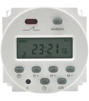
The Timer CN101A is a versatile programmable timer designed for controlling the timing of circuits. It allows users to set precise delays and timing sequences, making it ideal for automation and scheduling tasks. This component is widely used in applications such as lighting control, irrigation systems, industrial automation, and other time-based operations. Its user-friendly interface and reliable performance make it a popular choice for both hobbyists and professionals.
Explore Projects Built with Timer CN101A

Explore Projects Built with Timer CN101A
Technical Specifications
The Timer CN101A is equipped with robust features to ensure accurate and reliable timing. Below are its key technical details:
General Specifications
- Manufacturer: Timer
- Part ID: CN101A
- Operating Voltage: 220V AC (standard model) or 12V DC (optional model)
- Power Consumption: <2W
- Timing Range: 1 minute to 168 hours (7 days)
- Switching Capacity: 16A at 250V AC
- Accuracy: ±2 seconds per day
- Display: LCD screen for programming and status display
- Backup Battery: Built-in rechargeable battery for memory retention during power outages
- Operating Temperature: -10°C to 40°C
- Dimensions: 60mm x 60mm x 30mm
Pin Configuration and Descriptions
The Timer CN101A has a simple terminal block for wiring. Below is the pin configuration:
| Pin Number | Label | Description |
|---|---|---|
| 1 | L | Live input (AC power supply) |
| 2 | N | Neutral input (AC power supply) |
| 3 | NO | Normally Open terminal for load connection |
| 4 | COM | Common terminal for load connection |
| 5 | NC | Normally Closed terminal for load connection |
Note: The Normally Open (NO) and Normally Closed (NC) terminals allow for flexible control of connected devices, depending on the desired operation.
Usage Instructions
The Timer CN101A is straightforward to use and program. Follow the steps below to integrate it into your circuit:
Wiring Instructions
- Power Supply: Connect the live (L) and neutral (N) wires of the AC power supply to pins 1 and 2, respectively.
- Load Connection:
- For devices that should turn ON during the timer's active period, connect the load between the NO (pin 3) and COM (pin 4) terminals.
- For devices that should turn OFF during the timer's active period, connect the load between the NC (pin 5) and COM (pin 4) terminals.
- Ensure all connections are secure and insulated to prevent short circuits.
Programming the Timer
- Set the Current Time:
- Press and hold the "CLOCK" button.
- Use the "WEEK," "HOUR," and "MIN" buttons to set the current day, hour, and minute.
- Program ON/OFF Times:
- Press the "PROG" button to enter programming mode.
- Use the "WEEK," "HOUR," and "MIN" buttons to set the desired ON time.
- Press "PROG" again to set the OFF time for the same program.
- Repeat for additional programs (up to 16 ON/OFF settings).
- Activate the Timer:
- Press the "MANUAL" button to toggle between "ON," "OFF," and "AUTO" modes.
- Set to "AUTO" for the timer to follow the programmed schedule.
Important Considerations
- Ensure the load does not exceed the maximum switching capacity of 16A at 250V AC.
- Use proper fuses or circuit breakers for safety.
- Avoid exposing the timer to extreme temperatures or moisture.
Example: Controlling a Light with Arduino UNO
Although the CN101A is standalone, it can be used in conjunction with an Arduino UNO for advanced control. Below is an example of using the timer to control a light:
/*
  Example: Using Timer CN101A with Arduino UNO
  This code demonstrates how to monitor the timer's output state
  and control an LED accordingly.
*/

const int timerOutputPin = 7; // Pin connected to CN101A NO terminal
const int ledPin = 13;        // Pin connected to an LED

void setup() {
  pinMode(timerOutputPin, INPUT); // Set timer output pin as input
  pinMode(ledPin, OUTPUT);        // Set LED pin as output
}

void loop() {
  int timerState = digitalRead(timerOutputPin); // Read timer output state

  if (timerState == HIGH) {
    digitalWrite(ledPin, HIGH); // Turn on LED if timer is active
  } else {
    digitalWrite(ledPin, LOW);  // Turn off LED if timer is inactive
  }
}
Note: Ensure the timer's NO terminal is connected to the Arduino's input pin through a voltage divider or optocoupler if the timer operates at 220V AC.
Troubleshooting and FAQs
Common Issues
Timer Does Not Turn ON/OFF as Programmed:
- Ensure the timer is set to "AUTO" mode.
- Verify the current time and programmed ON/OFF times are correct.
- Check the backup battery to ensure it retains settings during power outages.
Load Does Not Operate:
- Confirm the wiring is correct and secure.
- Ensure the load does not exceed the timer's switching capacity.
- Check for blown fuses or tripped circuit breakers.
Display is Blank:
- Verify the power supply is connected and functioning.
- Check the backup battery and replace if necessary.
FAQs
Can the timer be used with DC loads? Yes, the 12V DC model of the CN101A can be used with DC loads. Ensure the load voltage and current are within the timer's specifications.
How many programs can be set? The CN101A supports up to 16 ON/OFF programs.
Does the timer retain settings during power outages? Yes, the built-in rechargeable battery ensures memory retention.
By following this documentation, users can effectively utilize the Timer CN101A for a wide range of applications.