
Cirkit Designer
Your all-in-one circuit design IDE
Home /
Component Documentation
How to Use ADS1220: Examples, Pinouts, and Specs
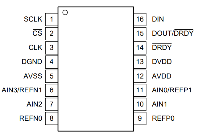
 Design with ADS1220 in Cirkit Designer
Introduction
The ADS1220 is a high-performance, 24-bit analog-to-digital converter (ADC) manufactured by Texas Instruments (TI). It is designed for precision measurement applications, offering a low-noise, low-drift architecture. The ADS1220 integrates programmable gain amplifiers (PGAs), a multiplexer, and an internal oscillator, making it an ideal choice for sensor interfacing and data acquisition systems.
Explore Projects Built with ADS1220
Arduino UNO and ADS1220-Based Precision Voltage Measurement System
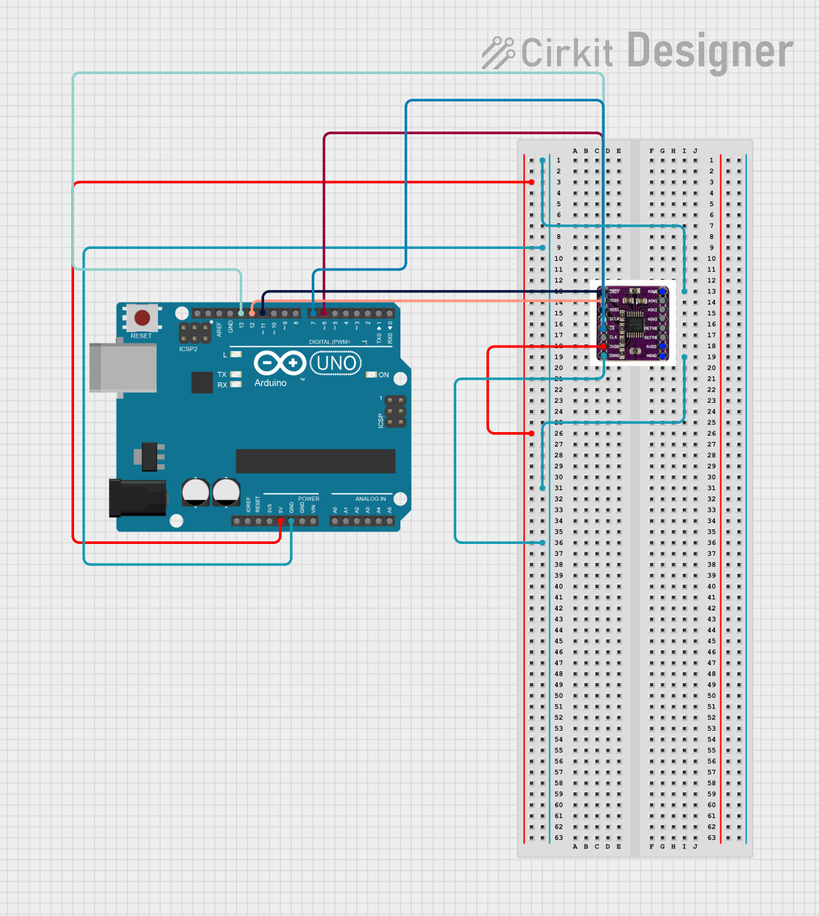
This circuit interfaces an Arduino UNO with an ADS1220 ADC to read analog voltage values. The Arduino communicates with the ADS1220 via SPI, and the ADC data is processed and printed to the serial monitor. The setup is designed for continuous voltage monitoring on channel 0 of the ADS1220.
Open Project in Cirkit DesignerESP32-Controlled Smart Lighting System with Power Monitoring
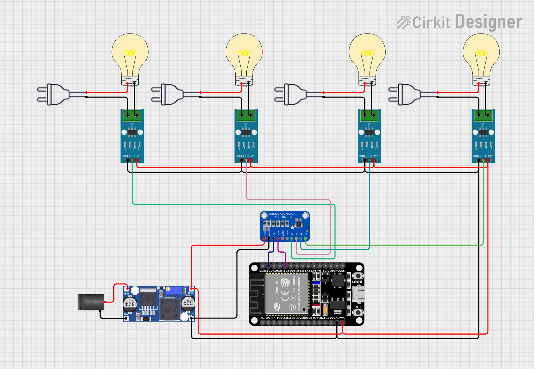
This circuit appears to be a multi-channel current monitoring system using several ACS712 current sensors to measure the current through different loads, likely bulbs connected to a 220V power source. The current readings from the sensors are digitized by an Adafruit ADS1115 16-bit ADC, which interfaces with an ESP32 microcontroller via I2C communication for further processing or telemetry. A buck converter is used to step down the voltage to power the ESP32 and the sensors, and the system is powered through a 2.1mm DC barrel jack, indicating it is designed for external power supply.
Open Project in Cirkit DesignerADS1115 and ACS712 Current Sensor-Based Voltage and Current Monitoring System
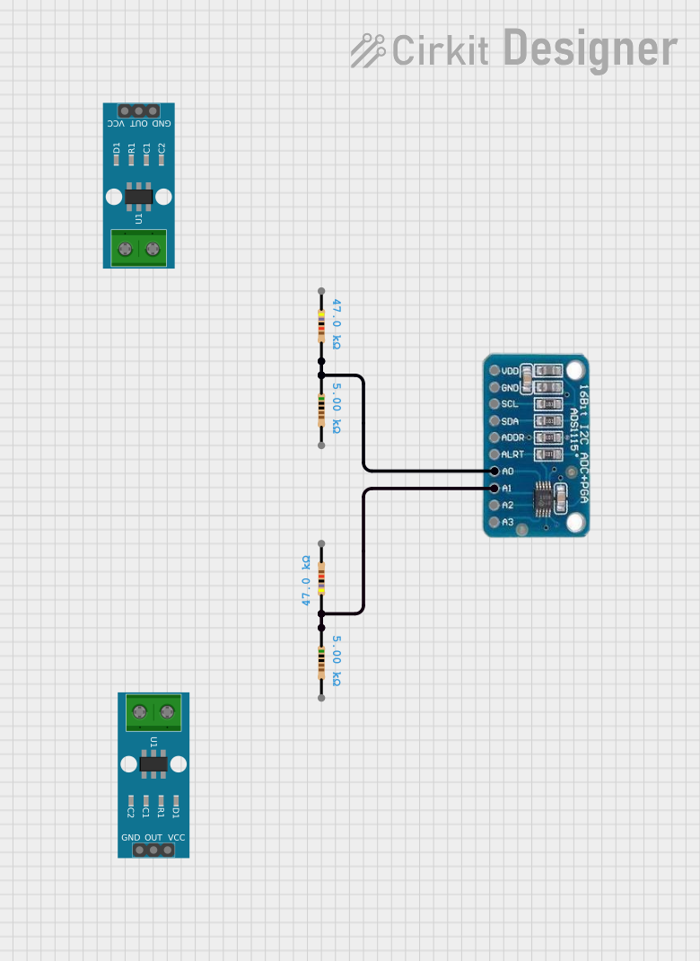
This circuit includes an ADS1115 analog-to-digital converter connected to two voltage divider networks formed by resistors. The voltage dividers are used to scale down the input voltages before they are read by the ADS1115 on channels A0 and A1.
Open Project in Cirkit DesignerBattery-Powered Arduino Nano Weather Station with LoRa Communication
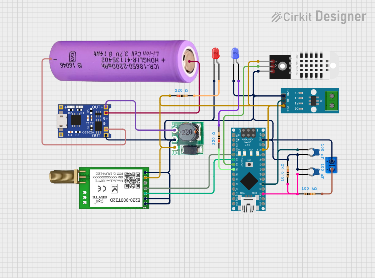
This circuit is a wireless sensor system that uses an Arduino Nano to collect data from a DHT22 temperature and humidity sensor and an ACS712 current sensor. The data is transmitted via an EBYTE LoRa E220 module, and the system is powered by a 18650 battery with a TP4056 charging module and a step-up boost converter to ensure a stable 5V supply.
Open Project in Cirkit DesignerExplore Projects Built with ADS1220
Arduino UNO and ADS1220-Based Precision Voltage Measurement System
This circuit interfaces an Arduino UNO with an ADS1220 ADC to read analog voltage values. The Arduino communicates with the ADS1220 via SPI, and the ADC data is processed and printed to the serial monitor. The setup is designed for continuous voltage monitoring on channel 0 of the ADS1220.
Open Project in Cirkit DesignerESP32-Controlled Smart Lighting System with Power Monitoring
This circuit appears to be a multi-channel current monitoring system using several ACS712 current sensors to measure the current through different loads, likely bulbs connected to a 220V power source. The current readings from the sensors are digitized by an Adafruit ADS1115 16-bit ADC, which interfaces with an ESP32 microcontroller via I2C communication for further processing or telemetry. A buck converter is used to step down the voltage to power the ESP32 and the sensors, and the system is powered through a 2.1mm DC barrel jack, indicating it is designed for external power supply.
Open Project in Cirkit DesignerADS1115 and ACS712 Current Sensor-Based Voltage and Current Monitoring System
This circuit includes an ADS1115 analog-to-digital converter connected to two voltage divider networks formed by resistors. The voltage dividers are used to scale down the input voltages before they are read by the ADS1115 on channels A0 and A1.
Open Project in Cirkit DesignerBattery-Powered Arduino Nano Weather Station with LoRa Communication
This circuit is a wireless sensor system that uses an Arduino Nano to collect data from a DHT22 temperature and humidity sensor and an ACS712 current sensor. The data is transmitted via an EBYTE LoRa E220 module, and the system is powered by a 18650 battery with a TP4056 charging module and a step-up boost converter to ensure a stable 5V supply.
Open Project in Cirkit DesignerCommon Applications
- Industrial process control
- Medical instrumentation (e.g., temperature or pressure sensors)
- Weigh scales and load cell measurements
- Portable instrumentation
- Thermocouple and RTD temperature measurements
Technical Specifications
Key Technical Details
| Parameter | Value |
|---|---|
| Resolution | 24-bit |
| Input Channels | 4 single-ended or 2 differential |
| Programmable Gain Amplifier | 1x to 128x |
| Data Rates | 20 SPS to 2000 SPS |
| Supply Voltage | 2.3 V to 5.5 V |
| Input Voltage Range | ±VREF / Gain |
| Reference Voltage | Internal or external (up to 5 V) |
| Interface | SPI |
| Operating Temperature Range | -40°C to +125°C |
| Package Options | TSSOP-16 |
Pin Configuration and Descriptions
The ADS1220 is available in a 16-pin TSSOP package. Below is the pinout and description:
| Pin No. | Name | Type | Description |
|---|---|---|---|
| 1 | AVDD | Power | Analog supply voltage (2.3 V to 5.5 V) |
| 2 | DVDD | Power | Digital supply voltage (1.65 V to 3.6 V) |
| 3 | GND | Ground | Ground reference for analog and digital circuits |
| 4 | AIN0 | Analog In | Analog input channel 0 |
| 5 | AIN1 | Analog In | Analog input channel 1 |
| 6 | AIN2 | Analog In | Analog input channel 2 |
| 7 | AIN3 | Analog In | Analog input channel 3 |
| 8 | REFP | Analog In | Positive reference input |
| 9 | REFN | Analog In | Negative reference input |
| 10 | DRDY/DOUT | Digital Out | Data ready output / SPI data output |
| 11 | SCLK | Digital In | SPI clock input |
| 12 | CS | Digital In | Chip select (active low) |
| 13 | DIN | Digital In | SPI data input |
| 14 | START | Digital In | Start conversion (active high) |
| 15 | RESET | Digital In | Reset input (active low) |
| 16 | NC | - | No connection |
Usage Instructions
How to Use the ADS1220 in a Circuit
- Power Supply: Connect AVDD and DVDD to appropriate supply voltages (e.g., 3.3 V for DVDD and 5 V for AVDD). Ensure GND is connected to the system ground.
- Input Configuration: Connect the analog inputs (AIN0–AIN3) to the desired sensors or signals. For differential measurements, use pairs of inputs (e.g., AIN0 and AIN1).
- Reference Voltage: Provide a stable reference voltage to REFP and REFN. Alternatively, use the internal reference by configuring the device via SPI.
- SPI Communication: Connect the SPI pins (SCLK, CS, DIN, and DRDY/DOUT) to a microcontroller or processor. Ensure proper SPI settings (Mode 1: CPOL = 0, CPHA = 1).
- Start Conversion: Use the START pin or send the appropriate SPI command to initiate conversions.
- Read Data: Monitor the DRDY pin for data-ready status, then read the conversion result via SPI.
Important Considerations
- Bypass Capacitors: Place decoupling capacitors (e.g., 0.1 µF and 10 µF) close to the AVDD and DVDD pins to reduce noise.
- Input Impedance: Ensure the source impedance is low enough to avoid signal degradation.
- Thermal Management: Operate the device within the specified temperature range to maintain accuracy.
- SPI Timing: Follow the timing requirements specified in the datasheet for reliable communication.
Example Code for Arduino UNO
Below is an example of interfacing the ADS1220 with an Arduino UNO via SPI:
#include <SPI.h>

// Pin definitions
#define CS_PIN 10    // Chip select pin
#define DRDY_PIN 9   // Data ready pin
#define START_PIN 8  // Start conversion pin

void setup() {
  // Initialize SPI
  SPI.begin();
  SPI.setDataMode(SPI_MODE1); // CPOL = 0, CPHA = 1
  SPI.setClockDivider(SPI_CLOCK_DIV16); // Adjust as needed for your setup

  // Configure pins
  pinMode(CS_PIN, OUTPUT);
  pinMode(DRDY_PIN, INPUT);
  pinMode(START_PIN, OUTPUT);

  // Set initial states
  digitalWrite(CS_PIN, HIGH);  // Deselect ADS1220
  digitalWrite(START_PIN, LOW); // Ensure conversion is stopped

  // Start conversion
  digitalWrite(START_PIN, HIGH);
}

void loop() {
  // Wait for data ready signal
  if (digitalRead(DRDY_PIN) == LOW) {
    digitalWrite(CS_PIN, LOW); // Select ADS1220

    // Read 3 bytes of data (24-bit result)
    byte data1 = SPI.transfer(0x00);
    byte data2 = SPI.transfer(0x00);
    byte data3 = SPI.transfer(0x00);

    digitalWrite(CS_PIN, HIGH); // Deselect ADS1220

    // Combine bytes into a 24-bit result
    long result = ((long)data1 << 16) | ((long)data2 << 8) | data3;

    // Print result to serial monitor
    Serial.println(result);
  }
}
Troubleshooting and FAQs
Common Issues
No Data Output:
- Ensure the SPI connections are correct and the SPI mode is set to Mode 1.
- Verify that the CS pin is toggled correctly during communication.
Incorrect Conversion Results:
- Check the reference voltage and ensure it is stable.
- Verify the input signal is within the specified range.
High Noise in Measurements:
- Use proper grounding and shielding techniques.
- Add bypass capacitors near the power supply pins.
Device Not Responding:
- Confirm that the RESET pin is not held low.
- Ensure the power supply voltages are within the specified range.
Tips for Troubleshooting
- Use an oscilloscope to verify SPI signals (SCLK, DIN, DOUT).
- Check the DRDY pin to ensure the device is completing conversions.
- Refer to the ADS1220 datasheet for detailed timing diagrams and configuration options.