Cirkit Designer Logo
Cirkit Designer
Your all-in-one circuit design IDE
Home / 
Component Documentation

How to Use Si7021: Examples, Pinouts, and Specs

Image of Si7021
Cirkit Designer LogoDesign with Si7021 in Cirkit Designer

Introduction

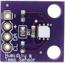
The Si7021 is a digital humidity and temperature sensor that provides accurate and reliable measurements with low power consumption. It features an I2C interface, making it easy to integrate into a wide range of applications. The sensor is commonly used in environmental monitoring, HVAC systems, weather stations, and IoT devices. Its compact design and high precision make it an excellent choice for applications requiring real-time temperature and humidity data.

Explore Projects Built with Si7021

Use Cirkit Designer to design, explore, and prototype these projects online. Some projects support real-time simulation. Click "Open Project" to start designing instantly!
Cellular-Enabled IoT Device with Real-Time Clock and Power Management
Image of LRCM PHASE 2 BASIC: A project utilizing Si7021 in a practical application
This circuit features a LilyGo-SIM7000G module for cellular communication and GPS functionality, interfaced with an RTC DS3231 for real-time clock capabilities. It includes voltage sensing through two voltage sensor modules, and uses an 8-channel opto-coupler for isolating different parts of the circuit. Power management is handled by a buck converter connected to a DC power source and batteries, with a fuse for protection and a rocker switch for on/off control. Additionally, there's an LED for indication purposes.
Cirkit Designer LogoOpen Project in Cirkit Designer
Solar-Powered Environmental Monitoring Station with GSM Reporting
Image of thesis nila po: A project utilizing Si7021 in a practical application
This is a solar-powered monitoring and control system with automatic power source selection, environmental sensing, and communication capabilities. It uses an ESP32 microcontroller to process inputs from gas, flame, and temperature sensors, and to manage outputs like an LCD display, LEDs, and a buzzer. The system can communicate via a SIM900A module and switch between solar and AC power sources using an ATS.
Cirkit Designer LogoOpen Project in Cirkit Designer
Satellite-Based Timing and Navigation System with SDR and Atomic Clock Synchronization
Image of GPS 시스템 측정 구성도_Confirm: A project utilizing Si7021 in a practical application
This circuit appears to be a complex system involving power supply management, GPS and timing synchronization, and data communication. It includes a SI-TEX G1 Satellite Compass for GPS data, an XHTF1021 Atomic Rubidium Clock for precise timing, and Ettus USRP B200 units for software-defined radio communication. Power is supplied through various SMPS units and distributed via terminal blocks and DC jacks. Data communication is facilitated by Beelink MINI S12 N95 computers, RS232 splitters, and a 1000BASE-T Media Converter for network connectivity. RF Directional Couplers are used to interface antennas with the USRP units, and the entire system is likely contained within cases for protection and organization.
Cirkit Designer LogoOpen Project in Cirkit Designer
Arduino Mega 2560 Based Security System with Fingerprint Authentication and SMS Alerts
Image of Door security system: A project utilizing Si7021 in a practical application
This circuit features an Arduino Mega 2560 microcontroller interfaced with a SIM800L GSM module, two fingerprint scanners, an I2C LCD display, an IR sensor, and a piezo buzzer. Power management is handled by a PowerBoost 1000 Basic Pad USB, a TP4056 charging module, and a Li-ion 18650 battery, with an option to use a Mini AC-DC 110V-230V to 5V 700mA module for direct power supply. The primary functionality appears to be a security system with GSM communication capabilities, biometric access control, and visual/audible feedback.
Cirkit Designer LogoOpen Project in Cirkit Designer

Explore Projects Built with Si7021

Use Cirkit Designer to design, explore, and prototype these projects online. Some projects support real-time simulation. Click "Open Project" to start designing instantly!
Image of LRCM PHASE 2 BASIC: A project utilizing Si7021 in a practical application
Cellular-Enabled IoT Device with Real-Time Clock and Power Management
This circuit features a LilyGo-SIM7000G module for cellular communication and GPS functionality, interfaced with an RTC DS3231 for real-time clock capabilities. It includes voltage sensing through two voltage sensor modules, and uses an 8-channel opto-coupler for isolating different parts of the circuit. Power management is handled by a buck converter connected to a DC power source and batteries, with a fuse for protection and a rocker switch for on/off control. Additionally, there's an LED for indication purposes.
Cirkit Designer LogoOpen Project in Cirkit Designer
Image of thesis nila po: A project utilizing Si7021 in a practical application
Solar-Powered Environmental Monitoring Station with GSM Reporting
This is a solar-powered monitoring and control system with automatic power source selection, environmental sensing, and communication capabilities. It uses an ESP32 microcontroller to process inputs from gas, flame, and temperature sensors, and to manage outputs like an LCD display, LEDs, and a buzzer. The system can communicate via a SIM900A module and switch between solar and AC power sources using an ATS.
Cirkit Designer LogoOpen Project in Cirkit Designer
Image of GPS 시스템 측정 구성도_Confirm: A project utilizing Si7021 in a practical application
Satellite-Based Timing and Navigation System with SDR and Atomic Clock Synchronization
This circuit appears to be a complex system involving power supply management, GPS and timing synchronization, and data communication. It includes a SI-TEX G1 Satellite Compass for GPS data, an XHTF1021 Atomic Rubidium Clock for precise timing, and Ettus USRP B200 units for software-defined radio communication. Power is supplied through various SMPS units and distributed via terminal blocks and DC jacks. Data communication is facilitated by Beelink MINI S12 N95 computers, RS232 splitters, and a 1000BASE-T Media Converter for network connectivity. RF Directional Couplers are used to interface antennas with the USRP units, and the entire system is likely contained within cases for protection and organization.
Cirkit Designer LogoOpen Project in Cirkit Designer
Image of Door security system: A project utilizing Si7021 in a practical application
Arduino Mega 2560 Based Security System with Fingerprint Authentication and SMS Alerts
This circuit features an Arduino Mega 2560 microcontroller interfaced with a SIM800L GSM module, two fingerprint scanners, an I2C LCD display, an IR sensor, and a piezo buzzer. Power management is handled by a PowerBoost 1000 Basic Pad USB, a TP4056 charging module, and a Li-ion 18650 battery, with an option to use a Mini AC-DC 110V-230V to 5V 700mA module for direct power supply. The primary functionality appears to be a security system with GSM communication capabilities, biometric access control, and visual/audible feedback.
Cirkit Designer LogoOpen Project in Cirkit Designer

Technical Specifications

The Si7021 sensor is designed to deliver high performance while maintaining simplicity in integration. Below are its key technical specifications:

General Specifications

Parameter Value
Supply Voltage (VDD) 1.9V to 3.6V
Average Current 150 µA (measuring)
Sleep Current 60 nA
Humidity Range 0% to 100% RH
Temperature Range -40°C to +125°C
Humidity Accuracy ±3% RH (typical)
Temperature Accuracy ±0.4°C (typical)
Communication Interface I2C
I2C Address 0x40 (default)

Pin Configuration

The Si7021 sensor has four pins, as described in the table below:

Pin Number Pin Name Description
1 VDD Power supply (1.9V to 3.6V)
2 GND Ground
3 SDA I2C data line
4 SCL I2C clock line

Usage Instructions

The Si7021 sensor is straightforward to use in a circuit, thanks to its I2C interface. Below are the steps and considerations for using the sensor:

Circuit Connection

  1. Connect the VDD pin to a 3.3V power supply (or a compatible voltage within the range of 1.9V to 3.6V).
  2. Connect the GND pin to the ground of your circuit.
  3. Connect the SDA pin to the I2C data line of your microcontroller.
  4. Connect the SCL pin to the I2C clock line of your microcontroller.
  5. Use pull-up resistors (typically 4.7kΩ) on the SDA and SCL lines if they are not already present in your circuit.

Arduino UNO Example

The Si7021 can be easily interfaced with an Arduino UNO. Below is an example code to read temperature and humidity data from the sensor:

#include <Wire.h>
#include "Adafruit_Si7021.h"

// Create an instance of the Si7021 sensor
Adafruit_Si7021 sensor = Adafruit_Si7021();

void setup() {
  Serial.begin(9600); // Initialize serial communication at 9600 baud
  Serial.println("Si7021 Sensor Test");

  if (!sensor.begin()) {
    Serial.println("Sensor not found. Check wiring!");
    while (true); // Halt execution if the sensor is not detected
  }
}

void loop() {
  // Read humidity and temperature from the sensor
  float humidity = sensor.readHumidity();
  float temperature = sensor.readTemperature();

  // Print the readings to the Serial Monitor
  Serial.print("Humidity: ");
  Serial.print(humidity);
  Serial.println(" %");

  Serial.print("Temperature: ");
  Serial.print(temperature);
  Serial.println(" °C");

  delay(2000); // Wait for 2 seconds before the next reading
}

Best Practices

  • Ensure the sensor is not exposed to direct sunlight or water, as this may affect its accuracy.
  • Avoid placing the sensor near heat sources or in areas with high airflow, as this can lead to inaccurate readings.
  • Use decoupling capacitors (e.g., 0.1 µF) near the VDD pin to stabilize the power supply.

Troubleshooting and FAQs

Common Issues

  1. Sensor not detected by the microcontroller:

    • Ensure the I2C address (default: 0x40) matches the address in your code.
    • Check the wiring, especially the SDA and SCL connections.
    • Verify that pull-up resistors are present on the I2C lines.
  2. Inaccurate readings:

    • Ensure the sensor is not exposed to contaminants like dust or moisture.
    • Allow the sensor to stabilize for a few seconds after powering it on.
  3. No data output:

    • Confirm that the power supply voltage is within the specified range (1.9V to 3.6V).
    • Check for loose or incorrect connections.

FAQs

Q: Can the Si7021 measure both temperature and humidity simultaneously?
A: Yes, the Si7021 can measure both parameters, but the measurements are taken sequentially.

Q: What is the maximum I2C clock speed supported by the Si7021?
A: The Si7021 supports I2C clock speeds up to 400 kHz.

Q: Is the Si7021 suitable for outdoor use?
A: While the Si7021 can be used outdoors, it should be protected from direct exposure to water and extreme environmental conditions.

Q: Can I use the Si7021 with a 5V microcontroller?
A: Yes, but you will need a level shifter to safely interface the 3.3V I2C lines with the 5V microcontroller.