How to Use Triple Output DC Power Supply: Examples, Pinouts, and Specs
Introduction
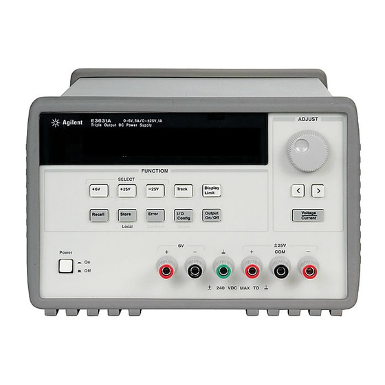
The Agilent E3631A Triple Output DC Power Supply is a versatile and reliable power source designed for a wide range of applications in electronics testing and circuit development. It offers three independent output channels, each with adjustable voltage and current settings, making it an ideal choice for laboratories, research institutions, and electronics manufacturing.
Explore Projects Built with Triple Output DC Power Supply


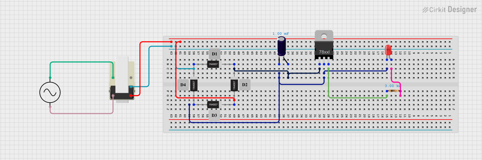
Explore Projects Built with Triple Output DC Power Supply
Common Applications and Use Cases
- Educational Laboratories: For teaching electronics and electrical engineering principles.
- Research and Development: Used in the development of new electronic devices and systems.
- Production Testing: Provides power for testing electronic components and PCBs.
- Service and Maintenance: Troubleshooting and repair of electronic equipment.
Technical Specifications
Key Technical Details
- Output Ratings (0 - 40°C):
- Channel 1: 0 to 6 V, 0 to 5 A
- Channel 2: 0 to 25 V, 0 to 1 A
- Channel 3: 0 to -25 V (negative output), 0 to 1 A
- Load and Line Regulation:
- Voltage: <0.01% + 2mV
- Current: <0.01% + 250µA
- Ripple & Noise (20 Hz to 20 MHz):
- Voltage RMS: 0.35 mV
- Peak-to-Peak: 3 mV
- Programming Accuracy (at 25°C ±5°C):
- Voltage: 0.05% + 10 mV
- Current: 0.1% + 10 mA
Pin Configuration and Descriptions
| Channel | Output Terminal | Description |
|---|---|---|
| 1 | +6V | Positive output up to 6V |
| 1 | COM | Common ground reference |
| 2 | +25V | Positive output up to 25V |
| 2 | COM | Common ground reference |
| 3 | -25V | Negative output up to -25V |
| 3 | COM | Common ground reference |
Usage Instructions
How to Use the Component in a Circuit
Initial Setup:
- Ensure the power supply is turned off before making any connections.
- Connect the power cord to the power supply and plug it into an appropriate AC outlet.
Connecting to a Circuit:
- Use appropriate cables to connect the output terminals to your circuit.
- Ensure that the polarity matches your circuit requirements.
Setting Output Values:
- Power on the E3631A.
- Select the desired channel using the front panel buttons.
- Adjust the voltage and current settings using the knobs or keypad.
Monitoring Outputs:
- The LCD display shows the set values and actual output for voltage and current.
- Monitor these values to ensure they match your circuit requirements.
Important Considerations and Best Practices
- Safety: Always follow standard safety procedures when working with electrical equipment.
- Load Matching: Ensure that the power supply's maximum output ratings are not exceeded by the connected load.
- Cooling: Allow sufficient ventilation around the power supply to prevent overheating.
- Grounding: Properly ground the power supply to avoid electrical hazards.
Troubleshooting and FAQs
Common Issues
No Output Voltage:
- Check if the power supply is turned on and properly connected to the AC source.
- Verify that the output terminals are securely connected to your circuit.
- Ensure that the output settings are correctly adjusted for your needs.
Inaccurate Output Voltage or Current:
- Calibrate the power supply regularly to maintain accuracy.
- Check for any load variations or circuit issues that may affect the readings.
Solutions and Tips for Troubleshooting
- If the power supply does not turn on, check the fuse and replace it if necessary.
- For output stability issues, verify that the power supply is not being overloaded or overheated.
- If the problem persists, refer to the Agilent E3631A service manual or contact technical support.
FAQs
Q: Can I use all three outputs simultaneously? A: Yes, the E3631A is designed to provide three independent outputs that can be used at the same time.
Q: How do I set the power supply to output a negative voltage? A: Use Channel 3, which is specifically designed to provide a negative output voltage up to -25V.
Q: What is the warranty period for the Agilent E3631A? A: The standard warranty period is typically one year, but it may vary by region. Check with Agilent for specific warranty information.
Note: This documentation is for informational purposes only and does not replace the official Agilent E3631A manual. Always refer to the official documentation for detailed instructions and safety information.