Cirkit Designer Logo
Cirkit Designer
Your all-in-one circuit design IDE
Home / 
Component Documentation

How to Use TB6560 Stepper Motor Driver: Examples, Pinouts, and Specs

Image of TB6560 Stepper Motor Driver
Cirkit Designer LogoDesign with TB6560 Stepper Motor Driver in Cirkit Designer

Introduction

The TB6560 is a microstepping driver designed for controlling bipolar stepper motors with high precision. It supports multiple microstepping resolutions and adjustable current settings, making it ideal for applications requiring precise movement and positioning. With a maximum current capacity of 3A per phase, the TB6560 is commonly used in CNC machines, 3D printers, robotics, and other motion control systems.

Explore Projects Built with TB6560 Stepper Motor Driver

Use Cirkit Designer to design, explore, and prototype these projects online. Some projects support real-time simulation. Click "Open Project" to start designing instantly!
CNC Machine Control System with Dual tb6600 Stepper Drivers and MAch3 USB Interface
Image of Jayshree CNC: A project utilizing TB6560 Stepper Motor Driver in a practical application
This circuit appears to be a control system for a CNC machine or similar automated equipment. It includes two tb6600 Micro Stepping Motor Drivers for controlling stepper motors, a DC power source with a step-down buck converter to provide the necessary voltage levels, and a 4-channel relay module for switching higher power loads. The MAch3 CNC USB interface suggests the system is designed to interface with computer numerical control software, and the RMCS_3001 BLDC Driver indicates the presence of a brushless DC motor control. The Tiva C launchpad microcontroller and various connectors imply that the system is modular and may be programmable for specific automation tasks.
Cirkit Designer LogoOpen Project in Cirkit Designer
Stepper Motor Control System with TB6600 Driver and DKC-1A Controller
Image of Copy of Copy of PLC-Based Step Motor Speed and Direction Control System: A project utilizing TB6560 Stepper Motor Driver in a practical application
This circuit controls a bipolar stepper motor using a tb6600 micro stepping motor driver and a DKC-1A stepper motor controller. The system is powered by a 24VDC power supply and includes a relay module for additional control functionalities.
Cirkit Designer LogoOpen Project in Cirkit Designer
Arduino Mega 2560 Controlled Multi-Stepper Motor System with DC Buck Step-down Power Supply
Image of Arduino Mega 2560 Controlled Stepper Motor System with DC Buck Step-down Power Supply: A project utilizing TB6560 Stepper Motor Driver in a practical application
This circuit is a stepper motor control system powered by a DC Buck Step-down power supply and controlled by an Arduino Mega 2560. It uses TB6600 and A4988 stepper motor drivers along with ULN2003A breakout boards to drive multiple stepper motors. The Arduino code initializes the pins and provides basic control functionality for the stepper motors.
Cirkit Designer LogoOpen Project in Cirkit Designer
ESP32 and TB6600/TB660 Stepper Motor Driver Joystick-Controlled Dual Stepper Motor System
Image of esp32_dual steppermotor: A project utilizing TB6560 Stepper Motor Driver in a practical application
This circuit controls two NEMA23 stepper motors using TB6600 and TB660 stepper motor drivers, interfaced with an ESP32 microcontroller. The ESP32 reads inputs from a KY-023 Dual Axis Joystick Module to control the direction and movement of the motors, with power supplied by a 12V power source and regulated by a Step Up Boost Power Converter.
Cirkit Designer LogoOpen Project in Cirkit Designer

Explore Projects Built with TB6560 Stepper Motor Driver

Use Cirkit Designer to design, explore, and prototype these projects online. Some projects support real-time simulation. Click "Open Project" to start designing instantly!
Image of Jayshree CNC: A project utilizing TB6560 Stepper Motor Driver in a practical application
CNC Machine Control System with Dual tb6600 Stepper Drivers and MAch3 USB Interface
This circuit appears to be a control system for a CNC machine or similar automated equipment. It includes two tb6600 Micro Stepping Motor Drivers for controlling stepper motors, a DC power source with a step-down buck converter to provide the necessary voltage levels, and a 4-channel relay module for switching higher power loads. The MAch3 CNC USB interface suggests the system is designed to interface with computer numerical control software, and the RMCS_3001 BLDC Driver indicates the presence of a brushless DC motor control. The Tiva C launchpad microcontroller and various connectors imply that the system is modular and may be programmable for specific automation tasks.
Cirkit Designer LogoOpen Project in Cirkit Designer
Image of Copy of Copy of PLC-Based Step Motor Speed and Direction Control System: A project utilizing TB6560 Stepper Motor Driver in a practical application
Stepper Motor Control System with TB6600 Driver and DKC-1A Controller
This circuit controls a bipolar stepper motor using a tb6600 micro stepping motor driver and a DKC-1A stepper motor controller. The system is powered by a 24VDC power supply and includes a relay module for additional control functionalities.
Cirkit Designer LogoOpen Project in Cirkit Designer
Image of Arduino Mega 2560 Controlled Stepper Motor System with DC Buck Step-down Power Supply: A project utilizing TB6560 Stepper Motor Driver in a practical application
Arduino Mega 2560 Controlled Multi-Stepper Motor System with DC Buck Step-down Power Supply
This circuit is a stepper motor control system powered by a DC Buck Step-down power supply and controlled by an Arduino Mega 2560. It uses TB6600 and A4988 stepper motor drivers along with ULN2003A breakout boards to drive multiple stepper motors. The Arduino code initializes the pins and provides basic control functionality for the stepper motors.
Cirkit Designer LogoOpen Project in Cirkit Designer
Image of esp32_dual steppermotor: A project utilizing TB6560 Stepper Motor Driver in a practical application
ESP32 and TB6600/TB660 Stepper Motor Driver Joystick-Controlled Dual Stepper Motor System
This circuit controls two NEMA23 stepper motors using TB6600 and TB660 stepper motor drivers, interfaced with an ESP32 microcontroller. The ESP32 reads inputs from a KY-023 Dual Axis Joystick Module to control the direction and movement of the motors, with power supplied by a 12V power source and regulated by a Step Up Boost Power Converter.
Cirkit Designer LogoOpen Project in Cirkit Designer

Common Applications:

  • CNC machines for precise cutting and engraving
  • 3D printers for accurate layer positioning
  • Robotics for controlled movement
  • Automated machinery and conveyor systems

Technical Specifications

The TB6560 stepper motor driver offers robust performance and flexibility. Below are its key technical details:

Key Specifications:

  • Input Voltage: 10V to 35V DC
  • Output Current: Up to 3A per phase (adjustable)
  • Microstepping Modes: Full step, 1/2 step, 1/8 step, 1/16 step
  • Control Signal Voltage: 3.3V to 5V logic compatible
  • Step Frequency: Up to 15kHz
  • Overcurrent Protection: Built-in
  • Overheat Protection: Built-in
  • Motor Type: Bipolar stepper motors

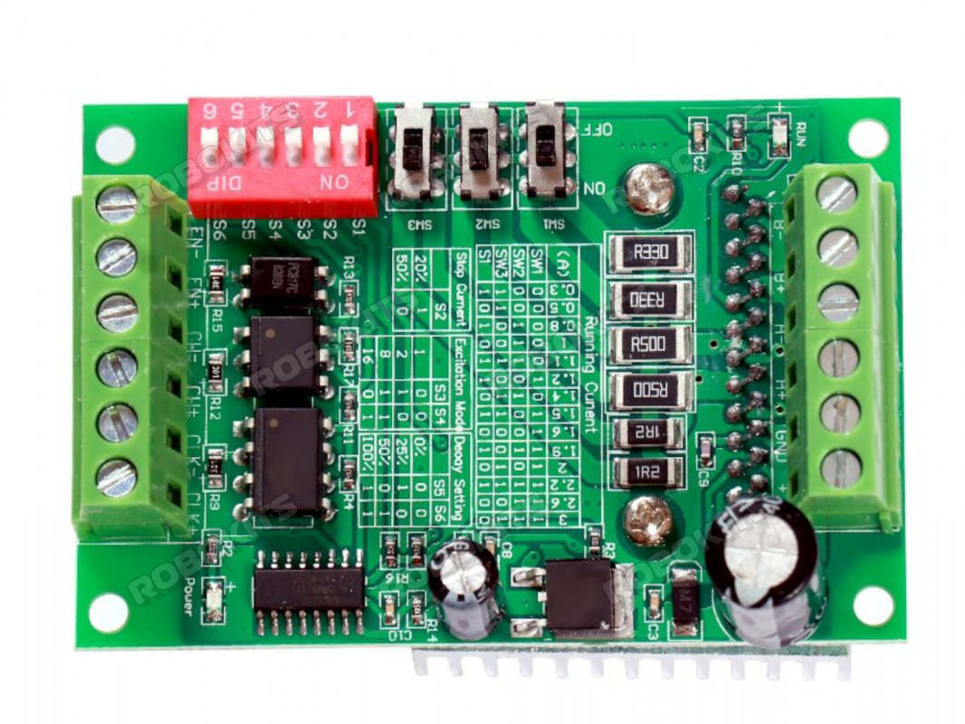
Pin Configuration and Descriptions:

The TB6560 driver typically has the following pinout:

Pin Name Description
ENA- Enable signal (active low). Disables the driver when pulled high.
DIR- Direction control signal. Determines the rotation direction of the motor.
PUL- Pulse signal. Each pulse moves the motor one step (or microstep).
GND Ground connection for control signals.
VCC Power supply for control signals (3.3V or 5V).
Motor A+ Positive terminal of motor coil A.
Motor A- Negative terminal of motor coil A.
Motor B+ Positive terminal of motor coil B.
Motor B- Negative terminal of motor coil B.
Power + Positive terminal for motor power supply (10V to 35V DC).
Power - Negative terminal for motor power supply (ground).

Usage Instructions

How to Use the TB6560 in a Circuit:

  1. Power Supply: Connect a DC power supply (10V to 35V) to the Power + and Power - terminals. Ensure the voltage matches the motor's requirements.
  2. Motor Connection: Connect the stepper motor's coils to the Motor A+, Motor A-, Motor B+, and Motor B- terminals. Verify the wiring matches the motor's datasheet.
  3. Control Signals: Connect the ENA-, DIR-, and PUL- pins to a microcontroller or control board (e.g., Arduino UNO). Use the GND and VCC pins to provide a common ground and logic voltage.
  4. Microstepping Settings: Adjust the DIP switches on the driver to set the desired microstepping mode and current limit. Refer to the TB6560 datasheet for switch configurations.
  5. Enable the Driver: Pull the ENA- pin low to enable the driver. Send pulses to the PUL- pin to move the motor.

Important Considerations:

  • Current Settings: Set the current limit to match the motor's rated current to avoid overheating or damaging the motor.
  • Cooling: Ensure proper heat dissipation for the TB6560 driver, as it can get hot during operation. Use a heatsink or fan if necessary.
  • Signal Voltage: Ensure the control signals are within the 3.3V to 5V range to avoid damaging the driver.

Example Code for Arduino UNO:

Below is an example of how to control a stepper motor using the TB6560 and an Arduino UNO:

// Define control pins for the TB6560 driver
const int dirPin = 2;  // Direction control pin
const int stepPin = 3; // Step pulse pin
const int enPin = 4;   // Enable pin

void setup() {
  // Set pin modes
  pinMode(dirPin, OUTPUT);
  pinMode(stepPin, OUTPUT);
  pinMode(enPin, OUTPUT);

  // Enable the driver
  digitalWrite(enPin, LOW); // Pull ENA- low to enable the driver
}

void loop() {
  // Set motor direction
  digitalWrite(dirPin, HIGH); // Set direction to clockwise

  // Generate step pulses
  for (int i = 0; i < 200; i++) { // Move 200 steps (1 revolution for a 1.8° motor)
    digitalWrite(stepPin, HIGH); // Send a high pulse
    delayMicroseconds(500);      // Wait 500 microseconds
    digitalWrite(stepPin, LOW);  // Send a low pulse
    delayMicroseconds(500);      // Wait 500 microseconds
  }

  delay(1000); // Wait 1 second before changing direction

  // Change direction
  digitalWrite(dirPin, LOW); // Set direction to counterclockwise

  // Generate step pulses
  for (int i = 0; i < 200; i++) { // Move 200 steps in the opposite direction
    digitalWrite(stepPin, HIGH);
    delayMicroseconds(500);
    digitalWrite(stepPin, LOW);
    delayMicroseconds(500);
  }

  delay(1000); // Wait 1 second before repeating
}

Troubleshooting and FAQs

Common Issues and Solutions:

  1. Motor Not Moving:

    • Check the power supply voltage and current rating.
    • Verify the motor wiring matches the datasheet.
    • Ensure the ENA- pin is pulled low to enable the driver.
  2. Motor Vibrates but Doesn't Rotate:

    • Check the microstepping settings on the DIP switches.
    • Verify the pulse signal frequency is within the driver's range.
  3. Driver Overheating:

    • Ensure the current limit is set correctly for the motor.
    • Add a heatsink or fan to improve cooling.
  4. Inconsistent Motor Movement:

    • Check for loose connections in the wiring.
    • Ensure the control signals are clean and free of noise.

FAQs:

  • Can the TB6560 drive unipolar stepper motors? No, the TB6560 is designed for bipolar stepper motors only.

  • What is the maximum step frequency supported? The TB6560 supports step frequencies up to 15kHz.

  • Can I use a 12V power supply with the TB6560? Yes, the TB6560 works with power supplies ranging from 10V to 35V. Ensure the motor is compatible with the chosen voltage.

  • How do I set the microstepping mode? Use the DIP switches on the driver to configure the microstepping mode. Refer to the TB6560 datasheet for detailed settings.