
How to Use DC Power Jack: Examples, Pinouts, and Specs
 Design with DC Power Jack in Cirkit Designer
Introduction
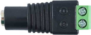
A DC power jack is a connector used to supply direct current (DC) power to electronic devices. It typically features a cylindrical shape and is designed to accept a matching DC power plug, allowing for easy connection and disconnection of power sources. DC power jacks are commonly found in consumer electronics, such as laptops, routers, and small appliances, as well as in DIY electronics projects.
Explore Projects Built with DC Power Jack
 Open Project in Cirkit Designer
 Open Project in Cirkit Designer
 Open Project in Cirkit Designer
 Open Project in Cirkit Designer
Explore Projects Built with DC Power Jack
Open Project in Cirkit DesignerOpen Project in Cirkit DesignerOpen Project in Cirkit DesignerOpen Project in Cirkit DesignerCommon Applications and Use Cases
- Powering Arduino boards, Raspberry Pi, and other microcontrollers
- Supplying power to small appliances and consumer electronics
- DIY electronics projects requiring a reliable DC power connection
- Prototyping circuits with external power supplies
Technical Specifications
Key Technical Details
- Voltage Rating: Typically 12V to 24V (varies by model)
- Current Rating: Commonly 1A to 5A
- Connector Type: Cylindrical barrel jack
- Outer Diameter (OD): Common sizes include 5.5mm, 3.5mm, or 2.1mm
- Inner Diameter (ID): Typically 2.1mm or 2.5mm
- Polarity: Center pin is usually positive (+), and the outer sleeve is negative (-)
- Mounting Style: Panel mount or PCB mount
- Material: Metal and plastic construction for durability
Pin Configuration and Descriptions
The DC power jack typically has three pins, as described in the table below:
| Pin Name | Description |
|---|---|
| Center Pin | Connects to the positive (+) terminal of the power supply. |
| Outer Sleeve | Connects to the negative (-) terminal of the power supply. |
| Switch Pin | Optional pin used to detect the presence of a plug or to switch power sources. |
Usage Instructions
How to Use the Component in a Circuit
- Identify the Polarity: Ensure the center pin of the DC power jack is connected to the positive terminal of the power supply, and the outer sleeve is connected to the negative terminal.
- Mounting: If using a panel-mount jack, secure it to the enclosure using the provided nut. For PCB-mount jacks, solder the pins to the PCB.
- Wiring: Connect the center pin to the positive rail of your circuit and the outer sleeve to the ground (GND).
- Switch Pin (Optional): If your jack has a switch pin, you can use it to detect when a plug is inserted or to switch between battery and external power.
Important Considerations and Best Practices
- Voltage and Current Ratings: Ensure the power jack can handle the voltage and current requirements of your circuit.
- Polarity: Double-check the polarity of the power supply to avoid damaging your components.
- Secure Connections: Use heat shrink tubing or electrical tape to insulate exposed wires and prevent short circuits.
- Compatibility: Verify that the plug matches the size and polarity of the jack.
Example: Connecting a DC Power Jack to an Arduino UNO
Below is an example of how to connect a DC power jack to an Arduino UNO using a 12V power supply.
// Example code for Arduino UNO powered via DC power jack
// This code blinks an LED connected to pin 13

void setup() {
  pinMode(13, OUTPUT); // Set pin 13 as an output
}

void loop() {
  digitalWrite(13, HIGH); // Turn the LED on
  delay(1000);            // Wait for 1 second
  digitalWrite(13, LOW);  // Turn the LED off
  delay(1000);            // Wait for 1 second
}
Note: Ensure the Arduino UNO's onboard voltage regulator can handle the input voltage from the DC power jack (e.g., 12V).
Troubleshooting and FAQs
Common Issues Users Might Face
No Power to the Circuit:
- Cause: Incorrect polarity or loose connections.
- Solution: Verify the polarity of the power supply and ensure all connections are secure.
Overheating:
- Cause: Exceeding the current rating of the power jack.
- Solution: Use a power jack with a higher current rating or reduce the load on the circuit.
Intermittent Power:
- Cause: Poor contact between the plug and jack.
- Solution: Ensure the plug is fully inserted and matches the jack's dimensions.
Short Circuit:
- Cause: Exposed wires or incorrect wiring.
- Solution: Insulate all connections and double-check the wiring.
Solutions and Tips for Troubleshooting
- Use a multimeter to check the voltage and polarity of the power supply.
- Inspect the jack and plug for physical damage or debris.
- Test the circuit with a different power supply to rule out issues with the power source.
- If using a PCB-mount jack, ensure all solder joints are clean and free of cold solder.
By following this documentation, you can effectively integrate a DC power jack into your electronic projects and troubleshoot common issues with ease.