How to Use MIDI Chassis connector: Examples, Pinouts, and Specs
Introduction
The MIDI (Musical Instrument Digital Interface) Chassis Connector is an integral component used in the interfacing of musical devices. It serves as the physical interface for MIDI signals, allowing electronic musical instruments, computers, and other related devices to communicate and synchronize with each other. Common applications include connecting keyboards, drum machines, sequencers, and computers to transfer MIDI data.
Explore Projects Built with MIDI Chassis connector
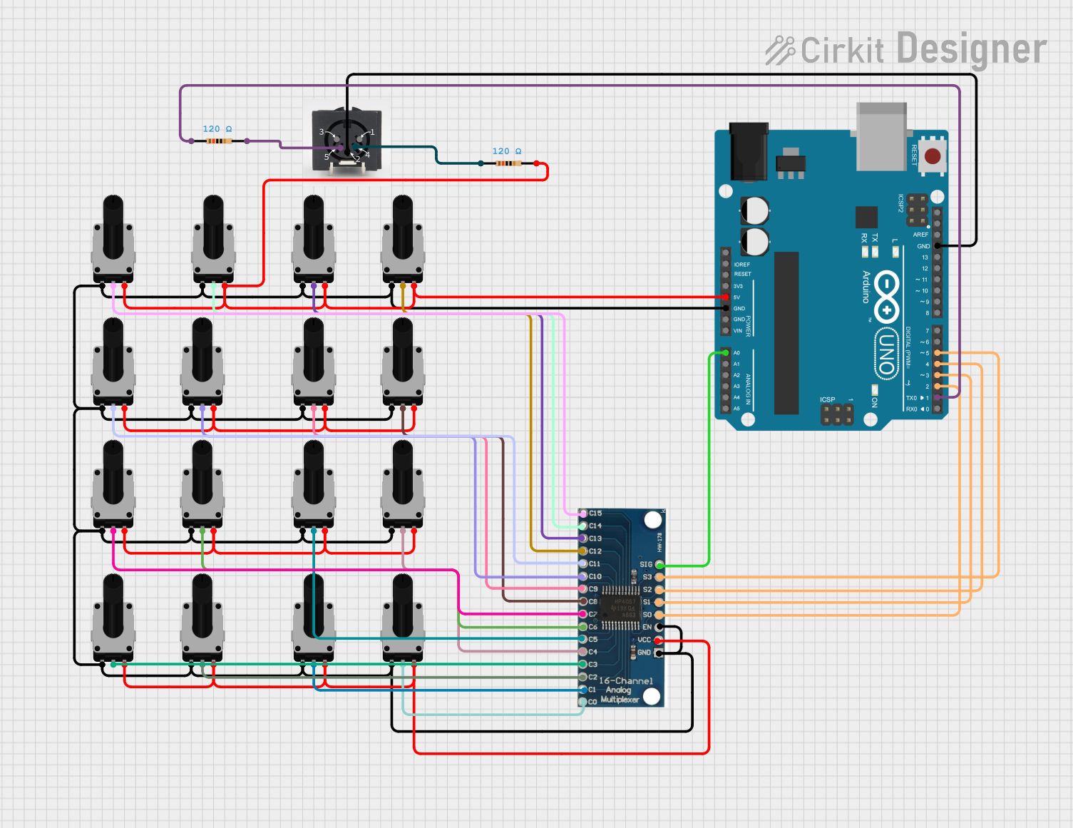

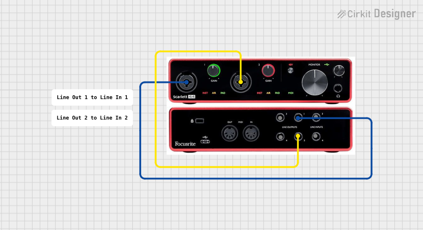
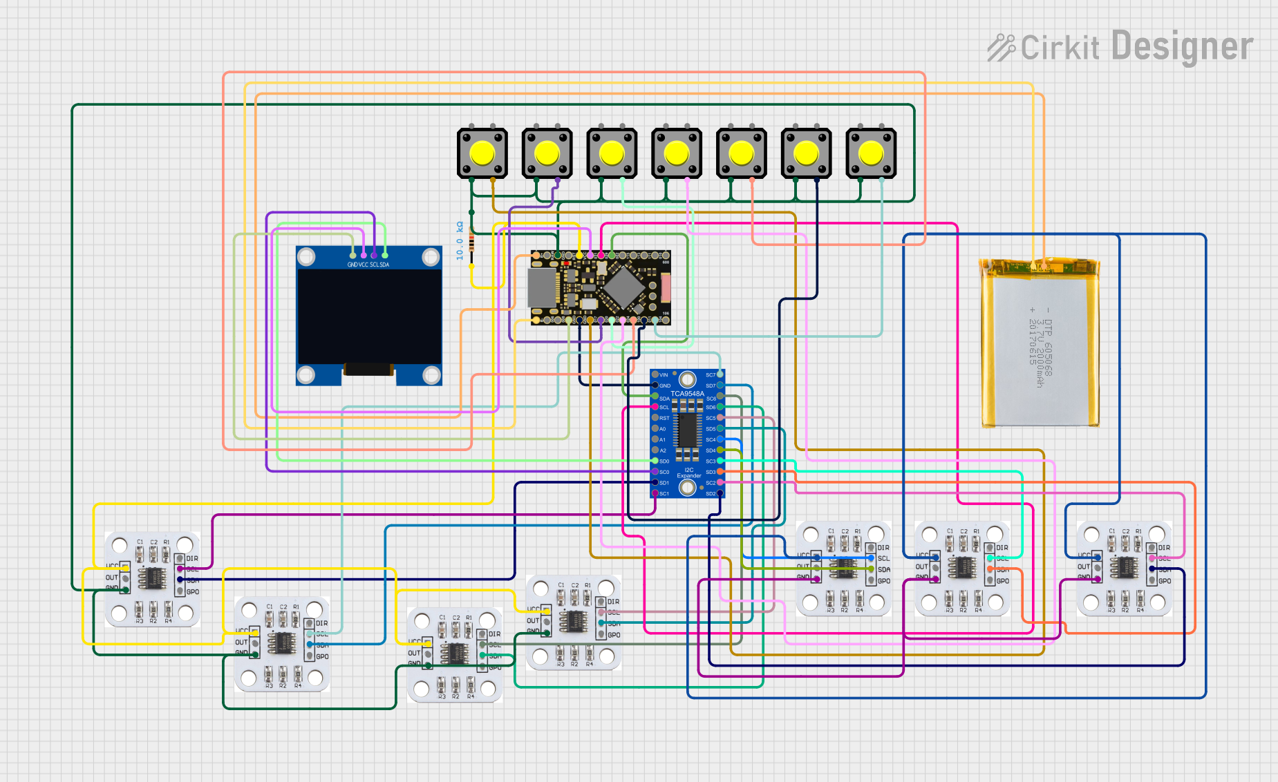
Explore Projects Built with MIDI Chassis connector
Technical Specifications
Key Technical Details
- Rated Voltage: 5V (typical MIDI operation voltage)
- Rated Current: 16 mA per pin (maximum)
- Contact Resistance: ≤ 30 mΩ (milliohms)
- Insulation Resistance: ≥ 100 MΩ (megohms)
- Durability: ≥ 5000 mating cycles
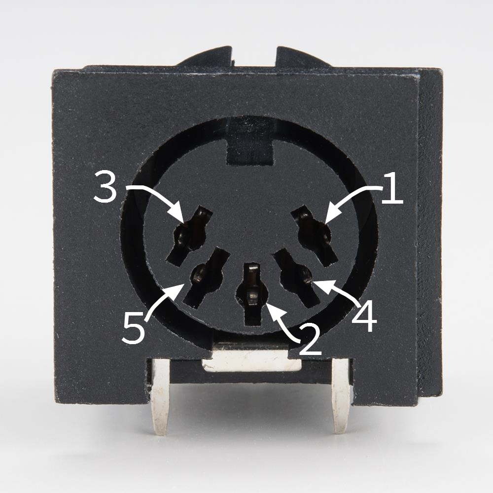
Pin Configuration and Descriptions
| Pin Number | Signal Name | Description |
|---|---|---|
| 1 | NC | Not connected; reserved for future use |
| 2 | Shield | Connected to the chassis ground |
| 3 | NC | Not connected; reserved for future use |
| 4 | MIDI Data - | MIDI data signal (inverted) |
| 5 | MIDI Data + | MIDI data signal (non-inverted) |
Note: Pins 1 and 3 are not connected in standard MIDI applications.
Usage Instructions
How to Use the Component in a Circuit
- Power Supply: Ensure that the MIDI device is powered with a stable 5V supply.
- Connection: Use a standard 5-pin MIDI cable to connect the MIDI Chassis Connector to other MIDI devices.
- Signal Routing: Connect pin 4 (MIDI Data -) and pin 5 (MIDI Data +) to the corresponding MIDI input or output circuitry of your device.
- Grounding: Connect pin 2 (Shield) to the device's chassis ground to minimize noise and interference.
Important Considerations and Best Practices
- Cable Quality: Use high-quality cables to ensure reliable data transmission.
- Grounding: Proper grounding is essential to prevent ground loops which can introduce noise into the MIDI signal.
- Avoid Physical Stress: Ensure that the connector is not subjected to excessive force or repeated bending which can lead to physical damage.
Troubleshooting and FAQs
Common Issues
- No Signal Transmission: Check the cable connections and ensure that the pins are not bent or damaged.
- Intermittent Connection: Inspect the connector for any signs of wear or damage. Replace if necessary.
- Noise in Signal: Verify that the chassis ground is properly connected.
Solutions and Tips for Troubleshooting
- Check Connections: Ensure all connections are secure and the pins are correctly aligned.
- Cable Test: Use a multimeter to test the continuity of the MIDI cable.
- Device Reset: Sometimes resetting the MIDI device can resolve communication issues.
FAQs
Q: Can I use a MIDI Chassis Connector with more than 5 pins? A: Standard MIDI uses a 5-pin connector. Additional pins are not used in the MIDI specification.
Q: Is it necessary to connect the shield to the chassis ground? A: Yes, it is recommended to connect the shield to the chassis ground to reduce noise.
Q: Can I use the MIDI Chassis Connector for non-MIDI applications? A: While it is designed for MIDI, it can be used for other applications if the specifications match the requirements.
Example Arduino Code
Below is an example of how to send a MIDI note on an Arduino UNO using the MIDI Chassis Connector:
#include <MIDI.h>

MIDI_CREATE_DEFAULT_INSTANCE();

void setup() {
  MIDI.begin(MIDI_CHANNEL_OMNI); // Listen to all MIDI channels
}

void loop() {
  // Send a Note On message at full velocity on MIDI channel 1
  MIDI.sendNoteOn(60, 127, 1); // Note number 60 (Middle C), Velocity 127, Channel 1
  delay(500); // Wait for 500ms
  MIDI.sendNoteOff(60, 0, 1); // Note number 60, Velocity 0, Channel 1
  delay(500); // Wait for 500ms
}
Note: This code assumes the use of a MIDI library for Arduino, such as the MIDI.h library, and that the Arduino is connected to the MIDI Chassis Connector with the correct pinout.
Remember to keep your code comments concise and within the 80 character line length limit.