How to Use Adafruit MPU6050: Examples, Pinouts, and Specs
Introduction
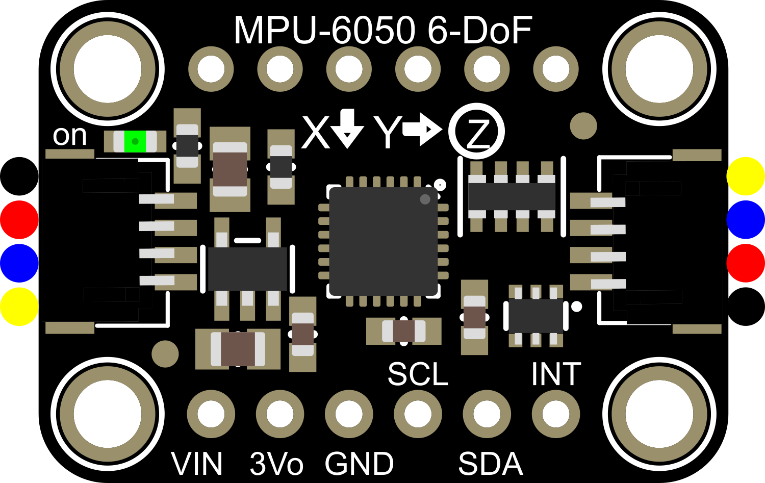
The Adafruit MPU6050 is a versatile 6-axis motion tracking module that integrates a 3-axis accelerometer and a 3-axis gyroscope into a single compact unit. This module communicates with microcontrollers via the I2C protocol, making it a popular choice for a wide range of applications including robotics, drones, gaming controllers, and various motion sensing devices. Its ability to measure both acceleration and rotational movements allows developers to capture complex motion data for real-time processing.
Explore Projects Built with Adafruit MPU6050

Explore Projects Built with Adafruit MPU6050
Technical Specifications
Key Features
- Accelerometer Ranges: ±2, ±4, ±8, ±16g
- Gyroscope Ranges: ±250, ±500, ±1000, ±2000°/sec
- Communication: I2C protocol
- Voltage Supply: 3.3V to 5V
- Current Consumption: 3.8mA (typical)
- Digital Output: 16-bit
- Operating Temperature: -40°C to +85°C
Pin Configuration and Descriptions
| Pin Number | Name | Description |
|---|---|---|
| 1 | VDD | Power supply (3.3V-5V) |
| 2 | GND | Ground |
| 3 | SCL | I2C clock line |
| 4 | SDA | I2C data line |
| 5 | XDA | Auxiliary I2C data (optional) |
| 6 | XCL | Auxiliary I2C clock (optional) |
| 7 | AD0 | I2C address selection (low: 0x68, high: 0x69) |
| 8 | INT | Interrupt output (optional) |
Usage Instructions
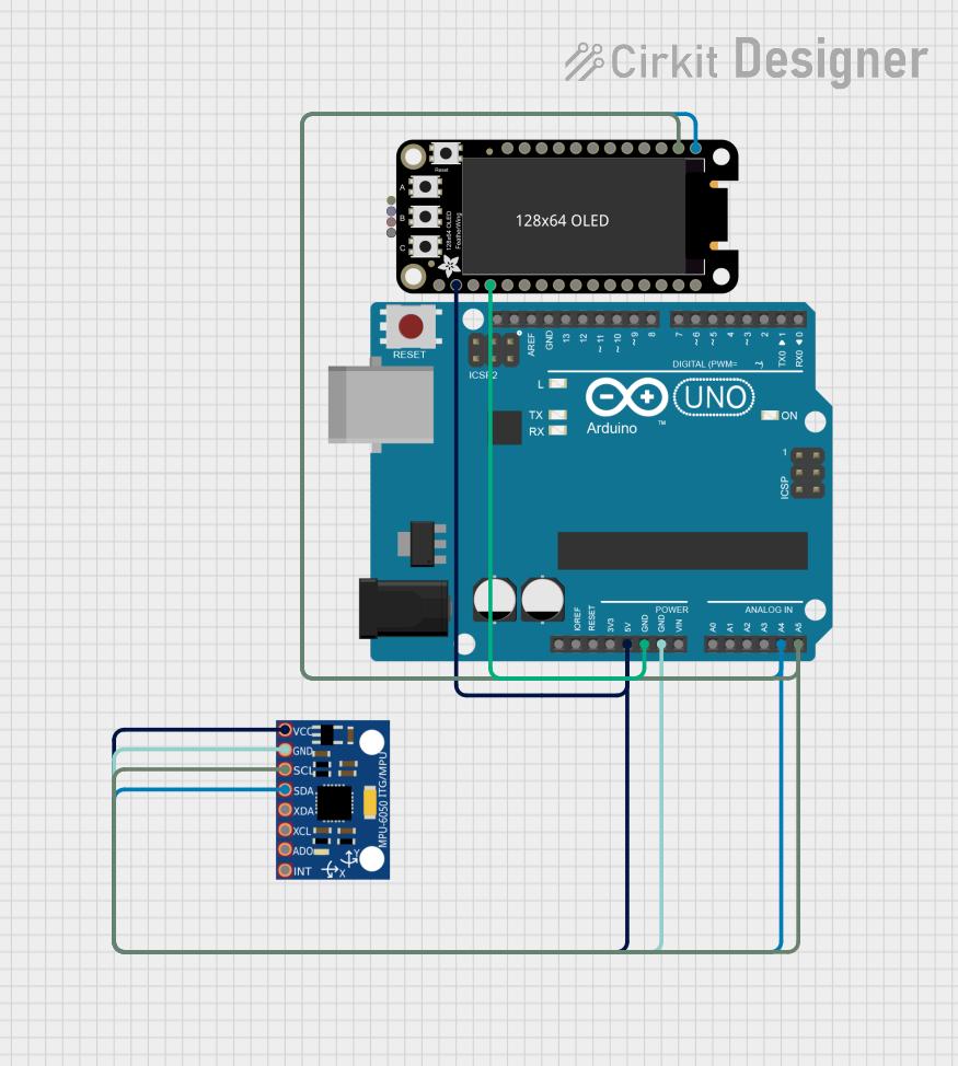
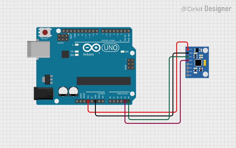
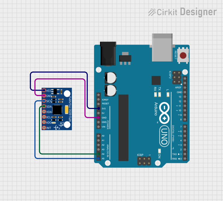
Interfacing with a Microcontroller
Powering the Module: Connect the VDD pin to a 3.3V or 5V supply from your microcontroller board and the GND pin to a common ground.
I2C Communication: Connect the SCL and SDA pins to the corresponding I2C clock and data lines on your microcontroller. If your microcontroller operates at 5V, ensure that the I2C lines are level-shifted to be compatible with the MPU6050's 3.3V logic.
Address Selection: The AD0 pin determines the I2C address of the MPU6050. Connect it to ground for the default address (0x68), or to VDD for an alternate address (0x69) if you are using multiple devices on the same I2C bus.
Interrupts (Optional): The INT pin can be connected to an interrupt-capable GPIO pin on your microcontroller if you wish to use the MPU6050's interrupt features.
Best Practices
- Use pull-up resistors on the I2C lines if they are not provided on the microcontroller board.
- Place the MPU6050 on a stable surface to minimize noise in the accelerometer and gyroscope readings.
- Calibrate the sensor for accurate readings. Calibration involves capturing the bias when the sensor is stationary and subtracting this bias from subsequent readings.
- Implement proper error handling in your code to address potential I2C communication failures.
Example Code for Arduino UNO
#include <Wire.h>
#include <Adafruit_MPU6050.h>
#include <Adafruit_Sensor.h>

Adafruit_MPU6050 mpu;

void setup() {
  Serial.begin(115200);
  while (!Serial) {
    delay(10); // wait for serial monitor to open
  }

  if (!mpu.begin()) {
    Serial.println("Failed to find MPU6050 chip");
    while (1) {
      delay(10);
    }
  }

  Serial.println("MPU6050 Found!");
  mpu.setAccelerometerRange(MPU6050_RANGE_8_G);
  mpu.setGyroRange(MPU6050_RANGE_500_DEG);
  mpu.setFilterBandwidth(MPU6050_BAND_21_HZ);
}

void loop() {
  /* Get new sensor events with the readings */
  sensors_event_t a, g, temp;
  mpu.getEvent(&a, &g, &temp);

  /* Print out the values */
  Serial.print("Acceleration X: ");
  Serial.print(a.acceleration.x);
  Serial.print(", Y: ");
  Serial.print(a.acceleration.y);
  Serial.print(", Z: ");
  Serial.print(a.acceleration.z);
  Serial.println(" m/s^2");

  Serial.print("Rotation X: ");
  Serial.print(g.gyro.x);
  Serial.print(", Y: ");
  Serial.print(g.gyro.y);
  Serial.print(", Z: ");
  Serial.print(g.gyro.z);
  Serial.println(" rad/s");

  Serial.print("Temperature: ");
  Serial.print(temp.temperature);
  Serial.println(" degC");

  delay(500);
}
Troubleshooting and FAQs
Common Issues
- Sensor Not Detected: Ensure that the wiring is correct and that the correct I2C address is being used in your code. Check for proper soldering and connections.
- Inaccurate Readings: Calibrate the sensor as mentioned in the best practices. Ensure that the MPU6050 is not subject to vibrations or movements during calibration.
- Noisy Data: Implement a filtering algorithm or increase the internal digital low pass filter bandwidth to smooth out the data.
FAQs
Q: Can I use the MPU6050 with a 5V microcontroller? A: Yes, but ensure that the I2C lines are level-shifted to be compatible with the MPU6050's 3.3V logic levels.
Q: How do I change the I2C address of the MPU6050? A: Connect the AD0 pin to VDD for address 0x69 or to GND for address 0x68.
Q: What is the purpose of the XDA and XCL pins? A: These pins are used for connecting auxiliary I2C devices, allowing them to share the MPU6050's I2C bus.
Q: How can I reduce the power consumption of the MPU6050? A: You can reduce power consumption by lowering the sampling rate or by putting the MPU6050 into sleep mode when not in use.
Q: Can I use multiple MPU6050 modules on the same I2C bus? A: Yes, you can use two MPU6050 modules on the same I2C bus by setting one to address 0x68 and the other to 0x69 using the AD0 pin.