How to Use FLYSKY RECEIVER: Examples, Pinouts, and Specs
Introduction
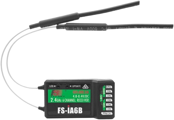
A Flysky receiver is a device used in remote control (RC) systems to receive signals transmitted by a Flysky transmitter. It decodes these signals and relays them to connected components, such as servos, electronic speed controllers (ESCs), or flight controllers. This enables precise remote operation of RC models, including drones, RC cars, boats, and airplanes.
Explore Projects Built with FLYSKY RECEIVER
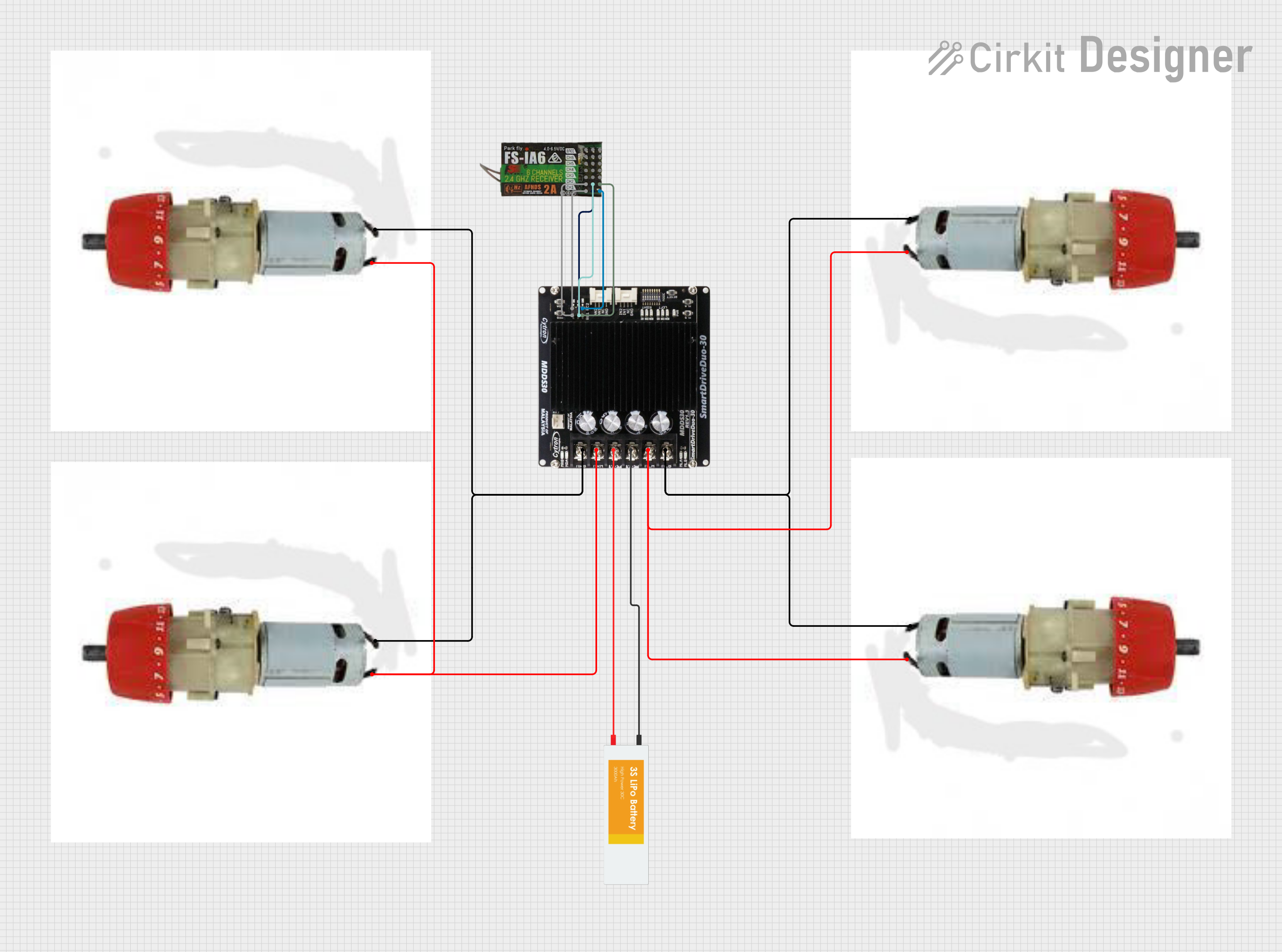
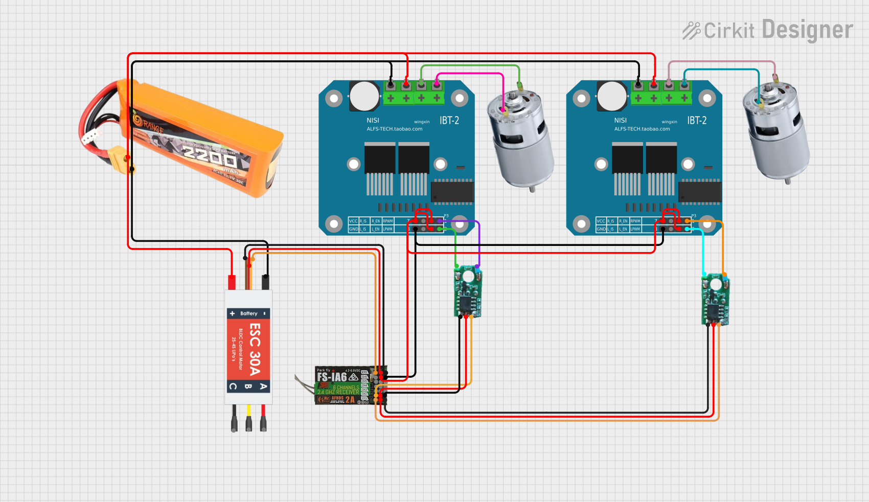
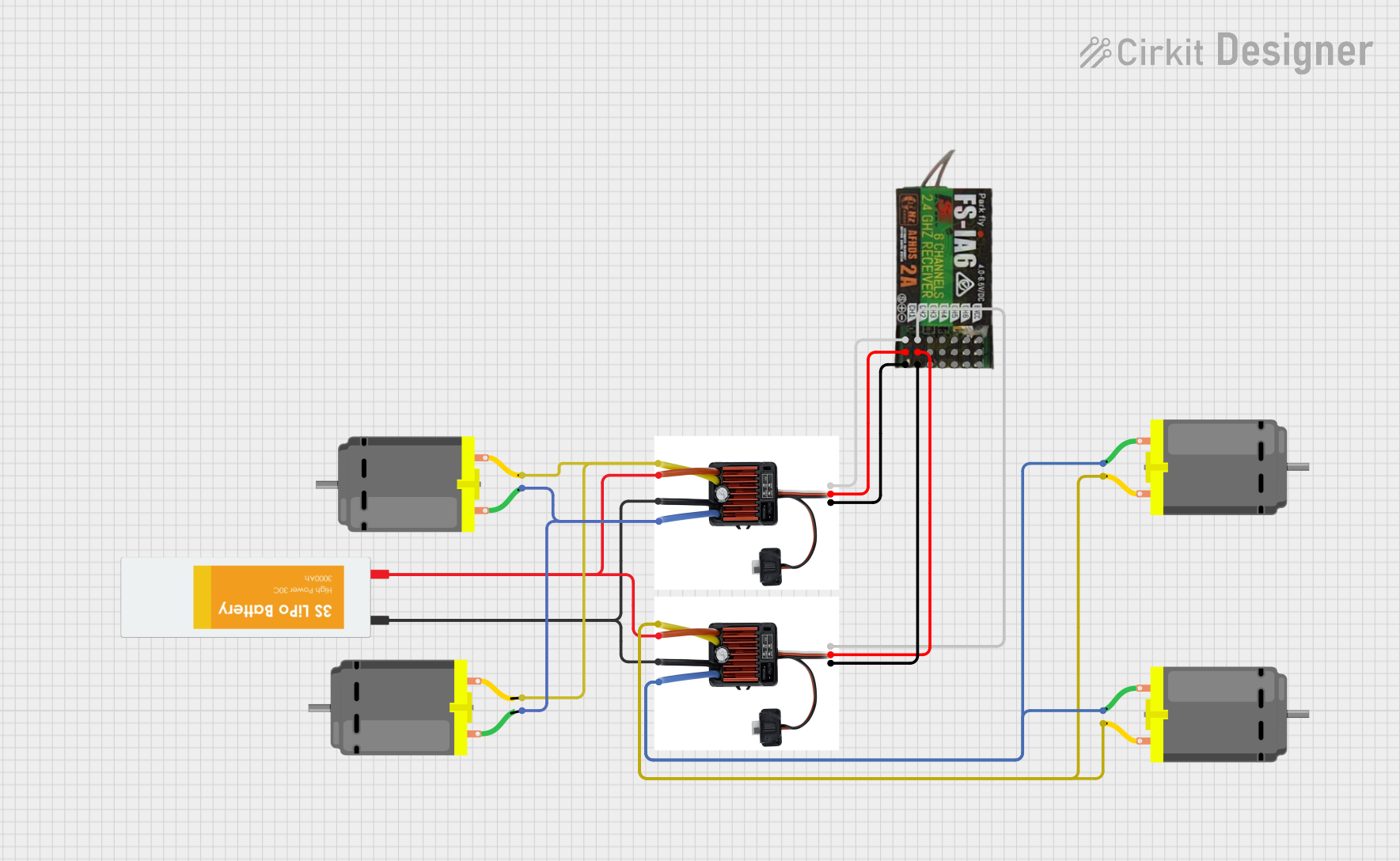
Explore Projects Built with FLYSKY RECEIVER
Common Applications and Use Cases
- Drones: Used to control flight operations via a transmitter.
- RC Cars: Enables remote steering and throttle control.
- RC Boats: Provides control over navigation and speed.
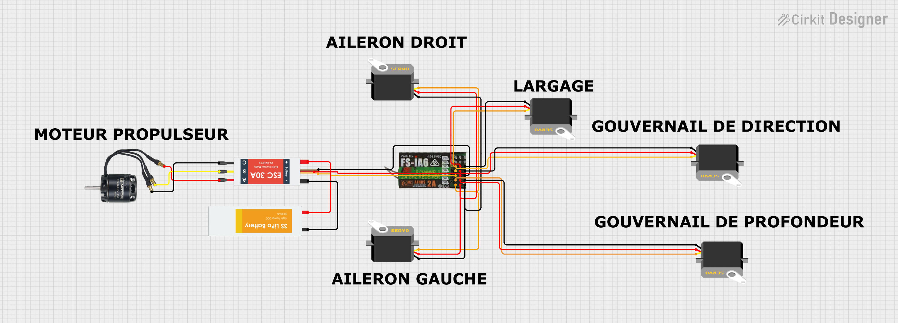
- RC Airplanes: Facilitates control of ailerons, elevators, rudders, and throttle.
- Robotics: Used in custom robotic projects requiring wireless control.
Technical Specifications
Below are the general technical specifications for a typical Flysky receiver. Note that specific models (e.g., FS-iA6B, FS-iA10B) may have slight variations.
| Specification | Details |
|---|---|
| Frequency Range | 2.4 GHz ISM band |
| Modulation Type | GFSK (Gaussian Frequency Shift Keying) |
| Channels | 6 to 10 (depending on the model) |
| Input Voltage Range | 4.0V - 6.5V |
| Signal Output | PWM, PPM, or iBUS (model-dependent) |
| Antenna | Dual antenna for enhanced signal range |
| Range | Up to 500 meters (line of sight) |
| Dimensions | Varies by model (e.g., 47x26x15mm for FS-iA6B) |
| Weight | ~10g |
Pin Configuration and Descriptions
The Flysky receiver typically has multiple pins for connecting servos, ESCs, or flight controllers. Below is a general pin configuration for a 6-channel receiver like the FS-iA6B:
| Pin Number | Label | Description |
|---|---|---|
| 1 | CH1 | Signal output for Channel 1 (e.g., throttle) |
| 2 | CH2 | Signal output for Channel 2 (e.g., steering) |
| 3 | CH3 | Signal output for Channel 3 |
| 4 | CH4 | Signal output for Channel 4 |
| 5 | CH5 | Signal output for Channel 5 |
| 6 | CH6 | Signal output for Channel 6 |
| 7 | B/VCC | Power input (4.0V - 6.5V) and ground connection |
Usage Instructions
How to Use the Flysky Receiver in a Circuit
Binding the Receiver to the Transmitter:
- Power on the receiver by connecting it to a power source (e.g., via a flight controller or ESC).
- Press and hold the "Bind" button on the receiver while powering it on. The LED will flash, indicating binding mode.
- On the Flysky transmitter, enter binding mode (refer to your transmitter's manual). The LED on the receiver will stop flashing and remain solid, indicating successful binding.
Connecting Components:
- Connect servos, ESCs, or flight controllers to the appropriate channel pins on the receiver.
- Ensure the polarity of the connections is correct (signal, power, and ground).
Powering the Receiver:
- Supply power to the receiver through the B/VCC pin. Ensure the voltage is within the specified range (4.0V - 6.5V).
Configuring the Transmitter:
- Set up the transmitter to match the number of channels and the desired control modes (e.g., PWM, PPM, or iBUS).
Important Considerations and Best Practices
- Antenna Placement: Ensure the receiver's antennas are positioned at 90-degree angles to each other for optimal signal reception.
- Power Supply: Use a stable power source to avoid signal loss or interference.
- Range Testing: Perform a range test before operating your RC model to ensure reliable communication.
- Signal Interference: Avoid operating in areas with high 2.4 GHz interference (e.g., near Wi-Fi routers).
Example: Using Flysky Receiver with Arduino UNO
The Flysky receiver can be connected to an Arduino UNO to read PWM signals. Below is an example code to read the PWM signal from Channel 1:
// Flysky Receiver - Reading PWM Signal on Channel 1
// Connect CH1 pin of the receiver to Arduino pin 2
// Ensure the receiver is powered with 5V and GND

const int receiverPin = 2;  // Pin connected to CH1
unsigned long pulseWidth;   // Variable to store pulse width

void setup() {
  pinMode(receiverPin, INPUT);  // Set receiver pin as input
  Serial.begin(9600);           // Initialize serial communication
}

void loop() {
  // Measure the duration of the HIGH pulse (PWM signal)
  pulseWidth = pulseIn(receiverPin, HIGH);

  // Print the pulse width in microseconds
  Serial.print("Pulse Width: ");
  Serial.print(pulseWidth);
  Serial.println(" us");

  delay(100);  // Small delay for readability
}
Troubleshooting and FAQs
Common Issues and Solutions
Receiver Not Binding to Transmitter:
- Ensure the receiver and transmitter are compatible (e.g., both support the same protocol like AFHDS 2A).
- Check that the receiver is in binding mode (LED should flash).
- Verify that the transmitter is in binding mode and within range.
No Signal Output:
- Confirm that the receiver is powered correctly (4.0V - 6.5V).
- Check the connections to the servos or ESCs for proper polarity.
- Ensure the transmitter is turned on and configured correctly.
Intermittent Signal Loss:
- Check the antenna placement and ensure it is not obstructed.
- Avoid operating in areas with high 2.4 GHz interference.
- Perform a range test to verify signal strength.
Receiver LED Not Lighting Up:
- Verify the power supply voltage and connections.
- Inspect the receiver for physical damage.
FAQs
Q: Can I use a Flysky receiver with other brands of transmitters?
A: Flysky receivers are designed to work with Flysky transmitters using the same protocol (e.g., AFHDS 2A). They are not compatible with other brands unless explicitly stated.Q: How many channels do I need for my RC model?
A: The number of channels depends on your model's requirements. For example, a basic RC car may need 2 channels (steering and throttle), while a drone may require 6 or more channels.Q: Can I use the Flysky receiver with a flight controller?
A: Yes, most flight controllers support Flysky receivers. Use the appropriate signal output mode (PWM, PPM, or iBUS) based on your flight controller's compatibility.Q: What is the range of a Flysky receiver?
A: The range is typically up to 500 meters in line-of-sight conditions, but this may vary depending on the environment and model.
By following this documentation, you can effectively use and troubleshoot your Flysky receiver for various RC applications.