How to Use ST7796: Examples, Pinouts, and Specs
Introduction
The ST7796, manufactured by Hosyond, is a TFT LCD controller designed to drive color displays. It supports a variety of resolutions and interfaces, making it a versatile choice for graphical user interfaces in embedded systems. The ST7796 is widely used in applications such as handheld devices, industrial control panels, and consumer electronics where vibrant and responsive displays are required.
Explore Projects Built with ST7796


Explore Projects Built with ST7796
Common Applications:
- Embedded systems with graphical user interfaces
- Industrial control panels
- Consumer electronics (e.g., smart home devices, handheld consoles)
- Portable medical devices
- Automotive dashboards and infotainment systems
Technical Specifications
Key Technical Details:
- Manufacturer: Hosyond
- Display Type: TFT LCD
- Resolution Support: Up to 480x320 pixels
- Color Depth: 16-bit and 18-bit color modes
- Interface: Parallel (8-bit/16-bit), SPI (4-wire)
- Operating Voltage: 2.8V to 3.3V
- Backlight Control: PWM or external control
- Operating Temperature: -30°C to 85°C
- Power Consumption: Low-power design for embedded systems
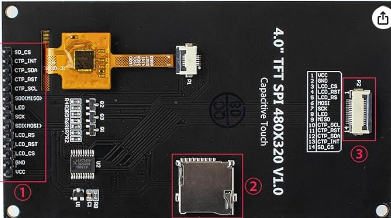
Pin Configuration and Descriptions:
The ST7796 controller typically interfaces with a microcontroller through a set of pins. Below is a table describing the common pin configuration:
| Pin Name | Type | Description |
|---|---|---|
| VCC | Power | Supply voltage (2.8V to 3.3V). |
| GND | Ground | Ground connection. |
| CS | Input | Chip Select: Active low signal to enable communication with the controller. |
| RESET | Input | Reset: Active low signal to reset the controller. |
| DC/RS | Input | Data/Command: Selects between data (high) and command (low) mode. |
| WR | Input | Write: Used in parallel interface mode to write data/commands. |
| RD | Input | Read: Used in parallel interface mode to read data. |
| DB0-DB15 | I/O | Data Bus: Used for parallel communication (8-bit or 16-bit mode). |
| SCL | Input | Serial Clock: Used in SPI mode for clock signal. |
| SDA | I/O | Serial Data: Used in SPI mode for data transfer. |
| BLK | Input | Backlight Control: Can be connected to PWM for brightness adjustment. |
| IM0-IM3 | Input | Interface Mode Selection: Configures the communication interface (SPI/Parallel). |
Note: The exact pinout may vary depending on the specific breakout board or module used with the ST7796.
Usage Instructions
How to Use the ST7796 in a Circuit:
- Power Supply: Connect the VCC pin to a 3.3V power source and GND to ground. Ensure the power supply is stable to avoid display flickering.
- Interface Selection: Configure the IM0-IM3 pins to select the desired communication interface (e.g., SPI or parallel). Refer to the datasheet for the correct configuration.
- Microcontroller Connection: Connect the data and control pins (e.g., CS, DC/RS, RESET) to the corresponding pins on your microcontroller.
- Backlight Control: Use the BLK pin to control the backlight. For adjustable brightness, connect it to a PWM-capable pin on the microcontroller.
- Initialization: Initialize the display by sending the appropriate commands to the ST7796. This includes setting the resolution, color depth, and display orientation.
Important Considerations:
- Voltage Levels: Ensure all signal lines are within the 3.3V logic level. Use level shifters if your microcontroller operates at 5V.
- Decoupling Capacitors: Place decoupling capacitors (e.g., 0.1µF) near the VCC and GND pins to reduce noise.
- Reset Signal: Always reset the display during power-up to ensure proper initialization.
- SPI vs. Parallel: SPI mode is slower but requires fewer pins, making it suitable for microcontrollers with limited GPIOs. Parallel mode offers faster data transfer but requires more pins.
Example Code for Arduino UNO (SPI Mode):
Below is an example of how to initialize and use the ST7796 with an Arduino UNO in SPI mode:
#include <Adafruit_GFX.h>    // Graphics library
#include <Adafruit_ST7796.h> // ST7796 driver library

// Define pin connections
#define TFT_CS   10  // Chip Select pin
#define TFT_DC   9   // Data/Command pin
#define TFT_RST  8   // Reset pin

// Create an instance of the ST7796 display
Adafruit_ST7796 tft = Adafruit_ST7796(TFT_CS, TFT_DC, TFT_RST);

void setup() {
  // Initialize serial communication for debugging
  Serial.begin(9600);
  Serial.println("Initializing ST7796...");

  // Initialize the display
  tft.init(240, 320); // Set resolution (e.g., 240x320)
  tft.setRotation(1); // Set display orientation (0-3)

  // Fill the screen with a color
  tft.fillScreen(ST77XX_BLUE);
  Serial.println("Display initialized!");
}

void loop() {
  // Draw a red rectangle
  tft.fillRect(50, 50, 100, 100, ST77XX_RED);

  // Add a delay
  delay(2000);

  // Clear the screen
  tft.fillScreen(ST77XX_BLACK);
  delay(2000);
}
Note: Ensure you have installed the
Adafruit_GFXandAdafruit_ST7796libraries in your Arduino IDE.
Troubleshooting and FAQs
Common Issues:
Display Not Turning On:
- Check the power supply and ensure the VCC and GND connections are secure.
- Verify that the RESET pin is properly connected and initialized.
Flickering or Distorted Display:
- Ensure the power supply is stable and free of noise.
- Check the data and control signal connections for loose or incorrect wiring.
No Response from the Display:
- Verify the interface mode (SPI/Parallel) is correctly configured using the IM0-IM3 pins.
- Ensure the microcontroller is sending commands at the correct voltage level (3.3V).
Backlight Not Working:
- Check the BLK pin connection. If using PWM, ensure the signal is properly configured.
Tips for Troubleshooting:
- Use a multimeter to check for continuity and proper voltage levels on all pins.
- Refer to the ST7796 datasheet for detailed timing and initialization requirements.
- Test the display with a known working example code to rule out software issues.
FAQ:
Q: Can I use the ST7796 with a 5V microcontroller?
A: Yes, but you must use level shifters to convert the 5V logic signals to 3.3V to avoid damaging the display.
Q: How do I adjust the brightness of the display?
A: Connect the BLK pin to a PWM-capable pin on your microcontroller and adjust the duty cycle to control brightness.
Q: What is the maximum resolution supported by the ST7796?
A: The ST7796 supports resolutions up to 480x320 pixels.