How to Use electro magnit: Examples, Pinouts, and Specs
Introduction
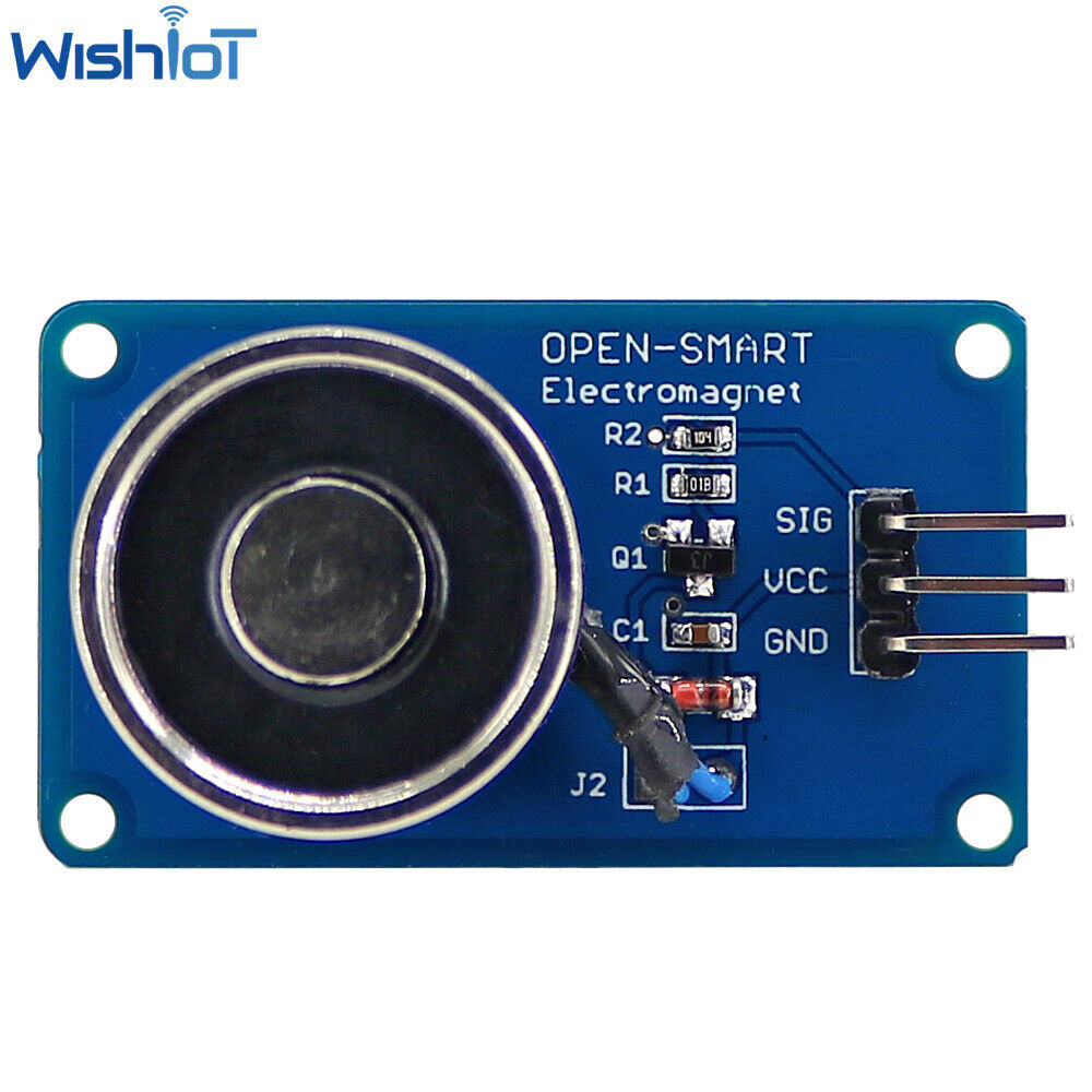
An electromagnet is a type of magnet in which the magnetic field is produced by an electric current. It consists of a coil of wire, often wrapped around a ferromagnetic core, which enhances the magnetic field when current flows through the wire. Unlike permanent magnets, the magnetic field of an electromagnet can be turned on or off by controlling the flow of current. This makes it highly versatile and widely used in various applications.
Explore Projects Built with electro magnit

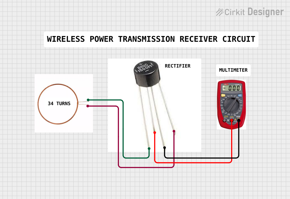
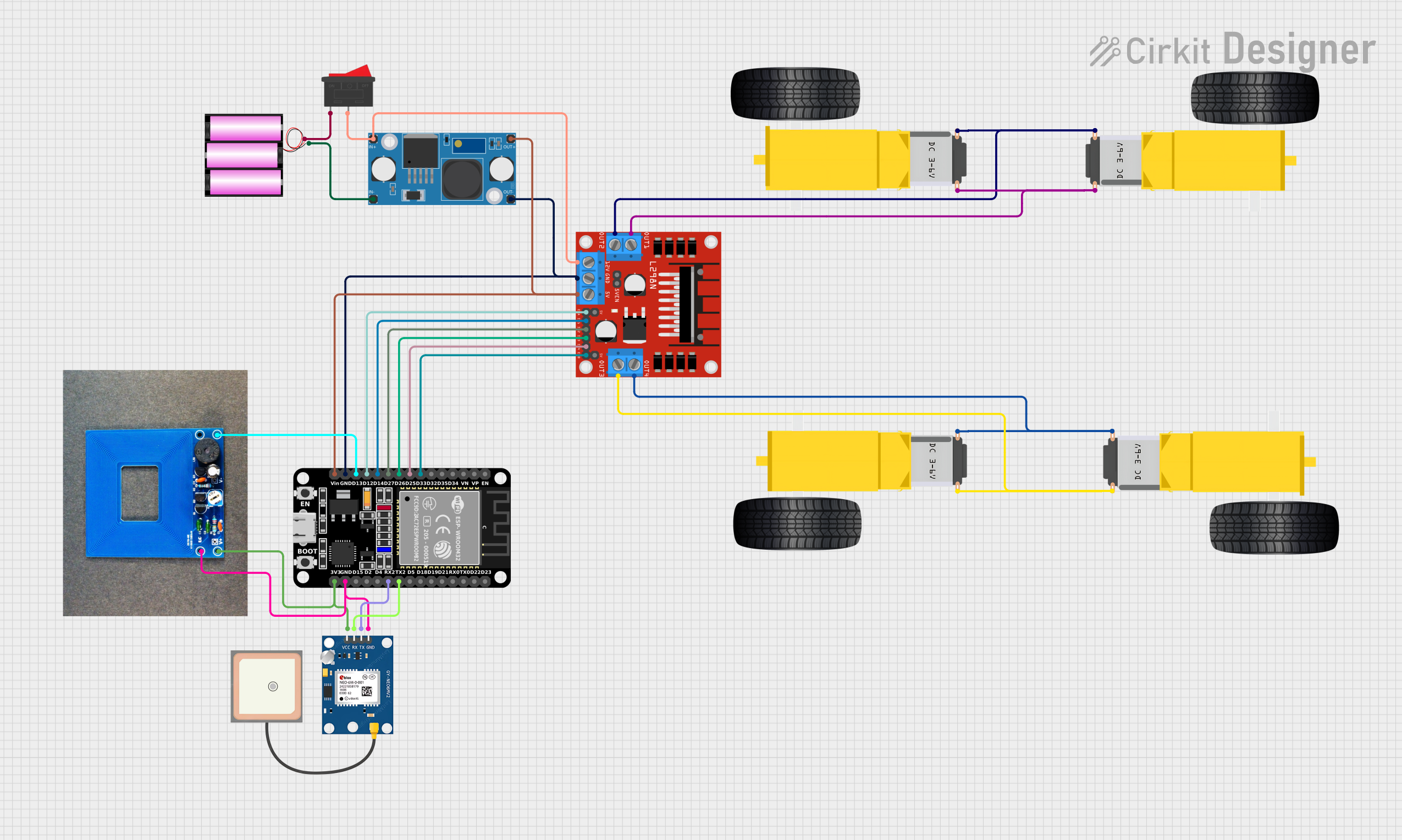
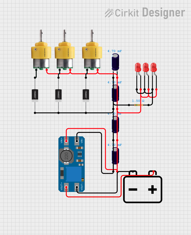
Explore Projects Built with electro magnit
Common Applications and Use Cases
- Electric motors and generators: Used to convert electrical energy into mechanical energy and vice versa.
- Relays and solenoids: Act as switches or actuators in electrical circuits.
- Magnetic lifting devices: Used in industries to lift heavy ferromagnetic materials.
- Magnetic locks: Found in security systems for doors and safes.
- Particle accelerators: Used to guide charged particles along specific paths.
- MRI machines: Generate strong magnetic fields for medical imaging.
Technical Specifications
Below are the general technical specifications for a typical electromagnet. Note that actual values may vary depending on the specific design and application.
Key Technical Details
- Operating Voltage: 5V to 24V DC (varies by design)
- Current Consumption: 0.5A to 5A (depending on coil resistance and voltage)
- Coil Resistance: 1Ω to 50Ω
- Magnetic Field Strength: Up to several Tesla (depending on core material and current)
- Core Material: Soft iron or other ferromagnetic materials
- Duty Cycle: Continuous or intermittent (check specific model for details)
Pin Configuration and Descriptions
Electromagnets typically have two terminals for electrical connections. These terminals are not polarized unless a diode is included for protection.
| Pin | Description |
|---|---|
| Pin 1 | Positive terminal (connect to power supply) |
| Pin 2 | Negative terminal (connect to ground) |
Usage Instructions
How to Use the Component in a Circuit
- Power Supply: Connect the electromagnet to a DC power supply within its operating voltage range. Ensure the power supply can provide sufficient current.
- Switching: Use a transistor, relay, or MOSFET to control the current flow through the electromagnet. This allows you to turn the magnetic field on or off.
- Protection: Add a flyback diode across the electromagnet terminals to protect the circuit from voltage spikes caused by the collapsing magnetic field when the current is turned off.
- Core Material: For maximum efficiency, use a ferromagnetic core to enhance the magnetic field strength.
Important Considerations and Best Practices
- Heat Management: Electromagnets can generate significant heat during operation. Ensure proper ventilation or heat dissipation to prevent overheating.
- Current Limiting: Use a resistor or current-limiting circuit to prevent excessive current draw, which could damage the electromagnet or power supply.
- Intermittent Use: For high-power electromagnets, avoid continuous operation to prevent overheating. Check the duty cycle rating.
- Polarity: If the electromagnet is used in a circuit with a diode, ensure correct polarity to avoid damage.
Example: Controlling an Electromagnet with Arduino UNO
Below is an example of how to control an electromagnet using an Arduino UNO and a transistor.
// Example: Controlling an electromagnet with Arduino UNO
// Components: Arduino UNO, NPN transistor (e.g., 2N2222), 1kΩ resistor, flyback diode,
// and a 12V electromagnet.

const int electromagnetPin = 9; // Pin connected to the transistor base via a resistor

void setup() {
  pinMode(electromagnetPin, OUTPUT); // Set the pin as an output
}

void loop() {
  digitalWrite(electromagnetPin, HIGH); // Turn on the electromagnet
  delay(1000); // Keep it on for 1 second
  digitalWrite(electromagnetPin, LOW);  // Turn off the electromagnet
  delay(1000); // Keep it off for 1 second
}
Circuit Connections:
- Connect the positive terminal of the electromagnet to the 12V power supply.
- Connect the negative terminal of the electromagnet to the collector of the NPN transistor.
- Connect the emitter of the transistor to ground.
- Place a flyback diode across the electromagnet terminals (cathode to positive terminal).
- Connect the base of the transistor to Arduino pin 9 through a 1kΩ resistor.
Troubleshooting and FAQs
Common Issues and Solutions
Electromagnet Not Turning On:
- Check the power supply voltage and current rating.
- Verify all connections, especially the transistor and resistor.
- Ensure the Arduino pin is set as an output and is providing the correct signal.
Overheating:
- Reduce the duty cycle or operating time.
- Use a heat sink or cooling mechanism for high-power electromagnets.
Voltage Spikes Damaging Components:
- Ensure a flyback diode is installed correctly across the electromagnet terminals.
Weak Magnetic Field:
- Increase the current (within safe limits) or use a better core material.
- Check for loose or corroded connections.
FAQs
Q: Can I use an AC power supply for an electromagnet?
A: Most electromagnets are designed for DC operation. Using AC may cause the magnetic field to alternate, which could be undesirable for certain applications.
Q: How do I calculate the magnetic field strength of an electromagnet?
A: The magnetic field strength (B) can be approximated using the formula:
B = (μ₀ * N * I) / L,
where μ₀ is the permeability of free space, N is the number of turns, I is the current, and L is the length of the coil.
Q: Can I use a battery to power an electromagnet?
A: Yes, but ensure the battery can provide sufficient current without draining too quickly. High-power electromagnets may require a more robust power source.
Q: Why is a flyback diode necessary?
A: A flyback diode protects the circuit from voltage spikes caused by the collapsing magnetic field when the current is turned off. This is essential to prevent damage to the transistor or other components.