How to Use ZMCT103C: Examples, Pinouts, and Specs
Introduction
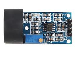
The ZMCT103C is a high-precision current sensor that utilizes a Hall effect sensing element to measure both AC and DC currents. It provides an isolated output voltage proportional to the current flowing through the conductor, ensuring safe and accurate current measurement. This component is widely used in applications such as power monitoring, energy management, motor control, and industrial automation systems.
Explore Projects Built with ZMCT103C


Explore Projects Built with ZMCT103C
Common Applications:
- Power monitoring in electrical systems
- Energy management in smart grids
- Motor control and protection
- Industrial automation and process control
- Battery management systems
Technical Specifications
The ZMCT103C is designed to deliver high accuracy and reliability in current sensing applications. Below are its key technical specifications:
| Parameter | Value |
|---|---|
| Measurement Range | 0–5A (typical) |
| Output Voltage Range | 0–5V (proportional to input current) |
| Supply Voltage | 5V DC |
| Accuracy | ±0.5% |
| Isolation Voltage | 2kV |
| Operating Temperature | -25°C to +70°C |
| Frequency Range | 50Hz–1kHz |
| Dimensions | 25mm x 25mm x 11mm |
Pin Configuration and Descriptions
The ZMCT103C has a simple pinout for easy integration into circuits. Below is the pin configuration:
| Pin | Name | Description |
|---|---|---|
| 1 | VCC | Power supply input (5V DC) |
| 2 | GND | Ground connection |
| 3 | VOUT | Output voltage proportional to the measured current |
Usage Instructions
How to Use the ZMCT103C in a Circuit
- Power Supply: Connect the VCC pin to a stable 5V DC power source and the GND pin to the ground of your circuit.
- Current Measurement: Pass the conductor carrying the current to be measured through the sensor's aperture. Ensure the conductor is properly aligned for accurate readings.
- Output Signal: The VOUT pin provides an analog voltage proportional to the current flowing through the conductor. This output can be connected to an ADC (Analog-to-Digital Converter) pin of a microcontroller for further processing.
Important Considerations and Best Practices
- Isolation: The ZMCT103C provides electrical isolation between the measured current and the output signal, ensuring safety in high-voltage applications.
- Calibration: For precise measurements, calibrate the sensor in your specific application environment.
- Filtering: Use a low-pass filter on the output signal to reduce noise, especially in high-frequency applications.
- Current Range: Ensure the current being measured does not exceed the sensor's maximum range (5A) to avoid saturation or damage.
Example: Connecting ZMCT103C to an Arduino UNO
Below is an example of how to connect the ZMCT103C to an Arduino UNO and read the current measurement:
Circuit Connections:
- Connect the VCC pin of the ZMCT103C to the 5V pin of the Arduino.
- Connect the GND pin of the ZMCT103C to the GND pin of the Arduino.
- Connect the VOUT pin of the ZMCT103C to the A0 analog input pin of the Arduino.
Arduino Code:
// ZMCT103C Current Sensor Example with Arduino UNO
// Reads the analog voltage from the sensor and calculates the current

const int sensorPin = A0; // Analog pin connected to VOUT of ZMCT103C
const float sensitivity = 5.0 / 1023.0; // ADC resolution (5V / 10-bit ADC)

void setup() {
  Serial.begin(9600); // Initialize serial communication
  Serial.println("ZMCT103C Current Sensor Test");
}

void loop() {
  int rawValue = analogRead(sensorPin); // Read raw ADC value
  float voltage = rawValue * sensitivity; // Convert to voltage
  float current = voltage; // Assuming 1V = 1A (calibration may be needed)

  // Print the results to the Serial Monitor
  Serial.print("Raw ADC Value: ");
  Serial.print(rawValue);
  Serial.print(" | Voltage: ");
  Serial.print(voltage, 3); // Print voltage with 3 decimal places
  Serial.print(" V | Current: ");
  Serial.print(current, 3); // Print current with 3 decimal places
  Serial.println(" A");

  delay(1000); // Wait for 1 second before the next reading
}
Notes:
- The above code assumes a linear relationship between the output voltage and the measured current. Adjust the calculation based on your specific calibration data.
- Use a multimeter to verify the sensor's output and ensure accurate readings.
Troubleshooting and FAQs
Common Issues and Solutions
No Output Voltage:
- Cause: Incorrect wiring or no current flowing through the conductor.
- Solution: Verify the connections and ensure the conductor is properly aligned in the sensor's aperture.
Inaccurate Readings:
- Cause: Noise in the output signal or improper calibration.
- Solution: Add a low-pass filter to the output and calibrate the sensor for your application.
Output Voltage Saturation:
- Cause: Current exceeds the sensor's maximum range (5A).
- Solution: Ensure the current being measured is within the specified range.
Fluctuating Readings:
- Cause: High-frequency noise or unstable power supply.
- Solution: Use a decoupling capacitor (e.g., 0.1µF) across the VCC and GND pins.
FAQs
Q1: Can the ZMCT103C measure DC currents?
Yes, the ZMCT103C can measure both AC and DC currents due to its Hall effect sensing element.
Q2: What is the maximum current the ZMCT103C can measure?
The ZMCT103C is designed to measure currents up to 5A. Exceeding this limit may result in inaccurate readings or damage to the sensor.
Q3: How do I calibrate the ZMCT103C?
To calibrate, pass a known current through the sensor and measure the output voltage. Use this data to determine the voltage-to-current conversion factor for your application.
Q4: Can I use the ZMCT103C with a 3.3V microcontroller?
Yes, but ensure the output voltage range of the sensor does not exceed the ADC input range of your microcontroller. You may need to scale the output voltage accordingly.
Q5: Is the ZMCT103C suitable for high-frequency applications?
The ZMCT103C is optimized for frequencies between 50Hz and 1kHz. For higher frequencies, additional filtering may be required.