How to Use converter: Examples, Pinouts, and Specs
Introduction
A converter is an electronic device designed to transform electrical energy from one form to another. This includes converting alternating current (AC) to direct current (DC), changing voltage levels, or even modifying frequency. Converters are essential in modern electronics, enabling compatibility between different power sources and devices.
Common applications of converters include:
- Power supplies for electronic devices (e.g., AC-DC adapters for laptops and phones)
- Voltage regulation in renewable energy systems (e.g., solar inverters)
- Motor control in industrial applications
- Battery charging systems
- DC-DC converters for portable electronics
Explore Projects Built with converter


Explore Projects Built with converter
Technical Specifications
The technical specifications of a converter vary depending on its type and application. Below is an example of a DC-DC step-down (buck) converter's specifications:
General Specifications
| Parameter | Value |
|---|---|
| Input Voltage Range | 4.5V to 28V |
| Output Voltage Range | 0.8V to 24V |
| Maximum Output Current | 3A |
| Efficiency | Up to 95% |
| Switching Frequency | 150 kHz to 1 MHz |
| Operating Temperature | -40°C to +85°C |
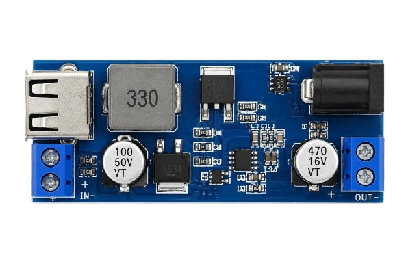
Pin Configuration
The following table describes the pinout of a typical DC-DC buck converter module:
| Pin Name | Description |
|---|---|
| VIN | Input voltage pin (connect to power source) |
| GND | Ground pin (common ground for input and output) |
| VOUT | Output voltage pin (connect to load) |
| EN | Enable pin (used to turn the converter on/off) |
| FB | Feedback pin (used for voltage regulation) |
Usage Instructions
How to Use the Converter in a Circuit
Connect the Input Voltage (VIN):
- Ensure the input voltage is within the specified range of the converter.
- Connect the positive terminal of the power source to the VIN pin and the negative terminal to the GND pin.
Set the Output Voltage (if adjustable):
- Many converters have a potentiometer or feedback pin to adjust the output voltage.
- Use a multimeter to measure the output voltage while adjusting the potentiometer.
Connect the Load:
- Attach the load to the VOUT pin and GND pin.
- Ensure the load does not exceed the maximum output current rating.
Enable the Converter:
- If the converter has an enable (EN) pin, connect it to a HIGH signal (e.g., 3.3V or 5V) to activate the converter.
Important Considerations and Best Practices
- Heat Dissipation: Converters can generate heat during operation. Use a heatsink or ensure proper ventilation if the converter operates at high currents.
- Input Voltage Protection: Use a fuse or diode to protect the converter from voltage spikes or reverse polarity.
- Output Filtering: Add capacitors to the output to reduce noise and improve stability.
- Avoid Overloading: Ensure the load does not exceed the converter's maximum current rating to prevent damage.
Example: Using a DC-DC Converter with Arduino UNO
Below is an example of connecting a DC-DC converter to power an Arduino UNO:
- Connect the input of the converter (VIN and GND) to a 12V power source.
- Adjust the output voltage of the converter to 5V using the potentiometer.
- Connect the output of the converter (VOUT and GND) to the Arduino's 5V and GND pins.
// Example Arduino code to blink an LED powered by a DC-DC converter

const int ledPin = 13; // Pin connected to the onboard LED

void setup() {
  pinMode(ledPin, OUTPUT); // Set the LED pin as an output
}

void loop() {
  digitalWrite(ledPin, HIGH); // Turn the LED on
  delay(1000);                // Wait for 1 second
  digitalWrite(ledPin, LOW);  // Turn the LED off
  delay(1000);                // Wait for 1 second
}
Troubleshooting and FAQs
Common Issues
No Output Voltage:
- Check if the input voltage is within the specified range.
- Ensure the enable (EN) pin is connected to a HIGH signal.
- Verify all connections are secure and correct.
Overheating:
- Ensure the load does not exceed the maximum current rating.
- Check for proper ventilation or add a heatsink.
Unstable Output Voltage:
- Add capacitors to the input and output for better filtering.
- Verify the feedback pin is correctly connected (if applicable).
Converter Not Turning On:
- Check the enable pin connection.
- Ensure the input polarity is correct.
FAQs
Q: Can I use a DC-DC converter to power sensitive electronics?
A: Yes, but ensure the output voltage is stable and within the device's operating range. Adding capacitors for filtering can help reduce noise.
Q: What happens if I exceed the maximum current rating?
A: Exceeding the current rating can cause the converter to overheat, shut down, or become permanently damaged.
Q: Can I use a converter to step up voltage?
A: Only if it is a step-up (boost) converter. A step-down (buck) converter cannot increase voltage.
Q: How do I know if my converter is efficient?
A: Check the efficiency rating in the datasheet. Higher efficiency means less energy is lost as heat.
By following these guidelines and best practices, you can effectively use a converter in your electronic projects.