How to Use ESC F65_128K: Examples, Pinouts, and Specs
Introduction
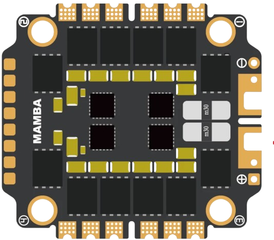
The ESC F65_128K is an advanced electronic speed controller (ESC) designed by FC for use with brushless motors. It is widely utilized in remote-controlled (RC) vehicles, drones, and other applications requiring precise motor control. This ESC is equipped with a 128K firmware, enabling advanced motor control features such as smooth acceleration, braking, and customizable settings to suit various performance needs.
Explore Projects Built with ESC F65_128K


Explore Projects Built with ESC F65_128K
Common Applications
- RC drones (racing, freestyle, and cinematic)
- RC cars and boats
- Robotics and automation systems
- Electric-powered model aircraft
Technical Specifications
Key Technical Details
| Parameter | Specification |
|---|---|
| Manufacturer | FC |
| Part ID | ESC F65_128K |
| Input Voltage Range | 2S–6S LiPo (7.4V–25.2V) |
| Continuous Current | 65A |
| Peak Current | 80A (for 10 seconds) |
| Firmware | 128K (BLHeli_32 compatible) |
| Motor Compatibility | Brushless motors (3-phase) |
| Signal Input | PWM, DShot150/300/600/1200 |
| BEC Output | None |
| Dimensions | 35mm x 20mm x 6mm |
| Weight | 12g |
| Operating Temperature | -20°C to 85°C |
| Protection Features | Overcurrent, overvoltage, and thermal |
Pin Configuration and Descriptions
| Pin Name | Description |
|---|---|
| Power Input (+) | Connect to the positive terminal of the LiPo battery. |
| Power Input (-) | Connect to the negative terminal of the LiPo battery. |
| Motor Phase A | Connect to one of the three motor wires (no specific order required). |
| Motor Phase B | Connect to one of the three motor wires (no specific order required). |
| Motor Phase C | Connect to one of the three motor wires (no specific order required). |
| Signal Input | Receives control signals (PWM or DShot) from the flight controller or RC. |
| Ground (GND) | Ground connection for the signal input. |
Usage Instructions
How to Use the ESC F65_128K in a Circuit
Power Connection:
- Connect the positive and negative terminals of the ESC to a compatible LiPo battery (2S–6S). Ensure the battery voltage matches the ESC's input voltage range.
Motor Connection:
- Connect the three motor wires to the ESC's Motor Phase A, B, and C pins. The order does not matter initially, as the motor direction can be adjusted later via firmware.
Signal Connection:
- Connect the Signal Input pin to the signal output of your flight controller or RC receiver.
- Connect the Ground (GND) pin to the ground of the flight controller or RC receiver.
Programming and Calibration:
- Use BLHeli_32 software to configure the ESC settings, such as motor direction, braking, and throttle response.
- Calibrate the throttle range if using PWM signals.
Testing:
- Power on the system and test the motor operation. Ensure the motor spins in the desired direction and responds correctly to throttle input.
Important Considerations and Best Practices
- Cooling: Ensure adequate airflow or cooling to prevent overheating during operation.
- Wiring: Use appropriately rated wires and connectors to handle the current draw.
- Firmware Updates: Regularly update the firmware using BLHeli_32 to access new features and improvements.
- Signal Type: For optimal performance, use DShot signals instead of PWM.
- Safety: Always disconnect the battery when making wiring changes to avoid short circuits or accidental motor starts.
Example Code for Arduino UNO
The ESC F65_128K can be controlled using PWM signals from an Arduino UNO. Below is an example code snippet to control the ESC:
#include <Servo.h> // Include the Servo library for generating PWM signals

Servo esc; // Create a Servo object to control the ESC

void setup() {
  esc.attach(9); // Attach the ESC signal wire to pin 9 on the Arduino
  esc.writeMicroseconds(1000); // Send minimum throttle signal (1000 µs)
  delay(2000); // Wait for 2 seconds to allow the ESC to initialize
}

void loop() {
  esc.writeMicroseconds(1500); // Send mid-throttle signal (1500 µs)
  delay(5000); // Run the motor at mid-throttle for 5 seconds

  esc.writeMicroseconds(1000); // Send minimum throttle signal (1000 µs)
  delay(5000); // Stop the motor for 5 seconds
}
Note: Adjust the throttle signal range (1000–2000 µs) based on your ESC's calibration.
Troubleshooting and FAQs
Common Issues and Solutions
Motor Does Not Spin:
- Cause: Incorrect wiring or signal input.
Solution: Verify the motor wires are connected to the ESC and the signal wire is properly connected to the flight controller or RC receiver.
- Cause: Incorrect wiring or signal input.
Motor Spins in the Wrong Direction:
- Cause: Motor phase wires are not in the correct order.
Solution: Swap any two motor phase wires or use BLHeli_32 software to reverse the motor direction.
- Cause: Motor phase wires are not in the correct order.
ESC Overheats:
- Cause: Insufficient cooling or excessive current draw.
Solution: Ensure proper airflow and verify the motor and propeller are within the ESC's current rating.
- Cause: Insufficient cooling or excessive current draw.
No Response from ESC:
- Cause: Incorrect signal type or throttle calibration.
Solution: Check the signal type (PWM or DShot) and recalibrate the throttle range.
- Cause: Incorrect signal type or throttle calibration.
Firmware Update Fails:
- Cause: Connection issue or incompatible software version.
Solution: Ensure the ESC is properly connected to the programming tool and use the latest version of BLHeli_32.
- Cause: Connection issue or incompatible software version.
FAQs
Can I use the ESC F65_128K with a brushed motor?
No, this ESC is designed specifically for brushless motors.What is the maximum supported LiPo cell count?
The ESC supports up to 6S LiPo batteries (25.2V).Does the ESC have a built-in BEC?
No, the ESC F65_128K does not include a BEC. Use an external BEC if needed.How do I update the firmware?
Use the BLHeli_32 software and a compatible USB programming tool to update the firmware.What signal types are supported?
The ESC supports PWM, DShot150, DShot300, DShot600, and DShot1200.
By following this documentation, users can effectively integrate and operate the ESC F65_128K in their projects.