How to Use 4 Button RF transmitter remote: Examples, Pinouts, and Specs
Introduction
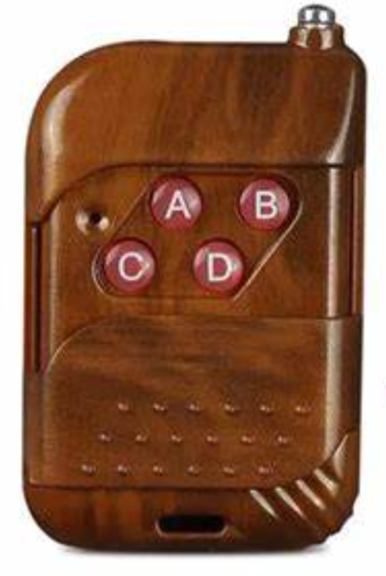
The 4 Button RF Transmitter Remote is a compact and versatile wireless control device designed to transmit radio frequency (RF) signals. It features four buttons, each capable of sending unique signals to a compatible RF receiver. This remote is commonly used in applications such as remote-controlled lighting, motorized gates, home automation systems, and other wireless control systems.
By utilizing RF technology, the remote can operate over a considerable range without requiring a direct line of sight, making it ideal for both indoor and outdoor use.
Explore Projects Built with 4 Button RF transmitter remote
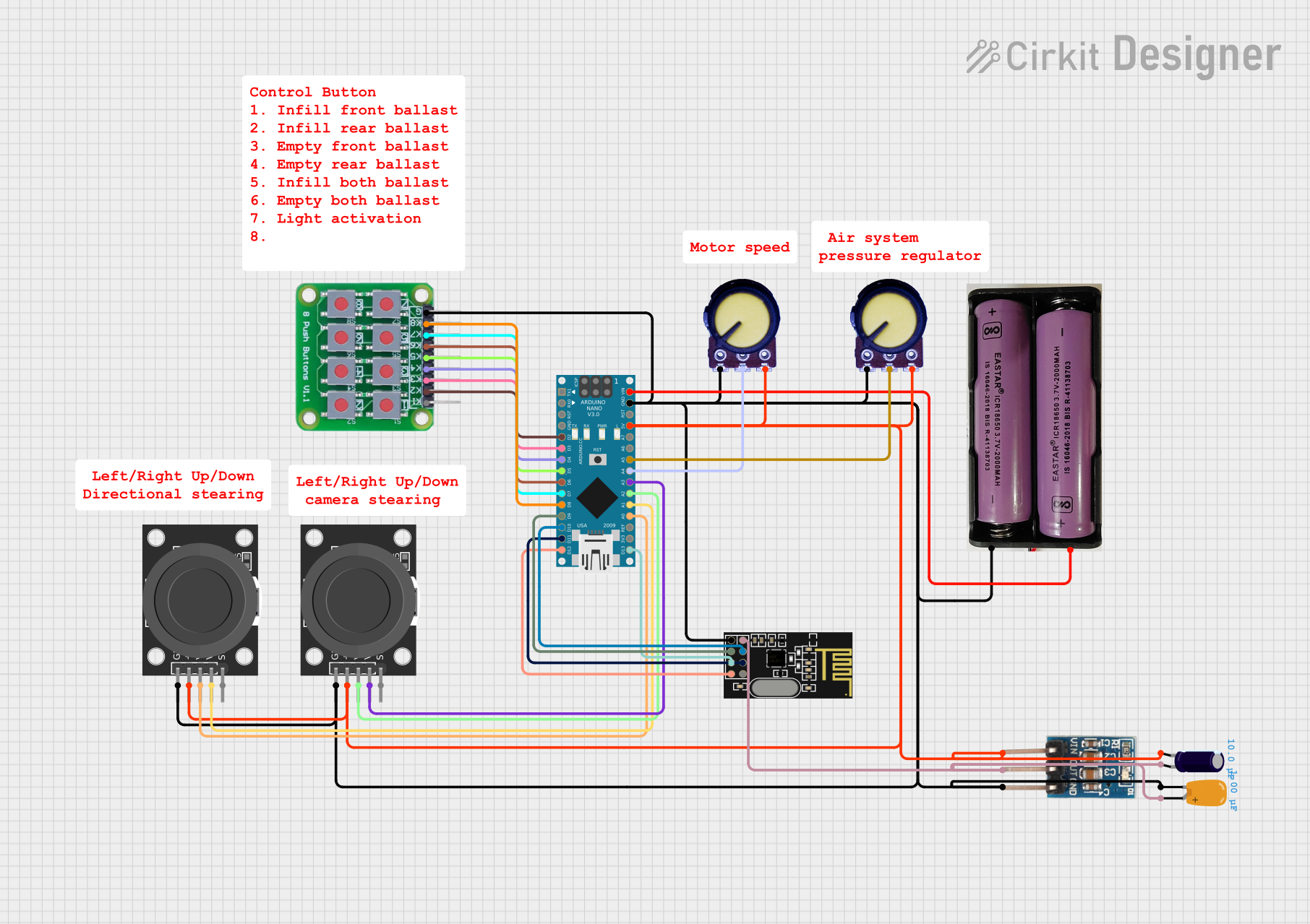

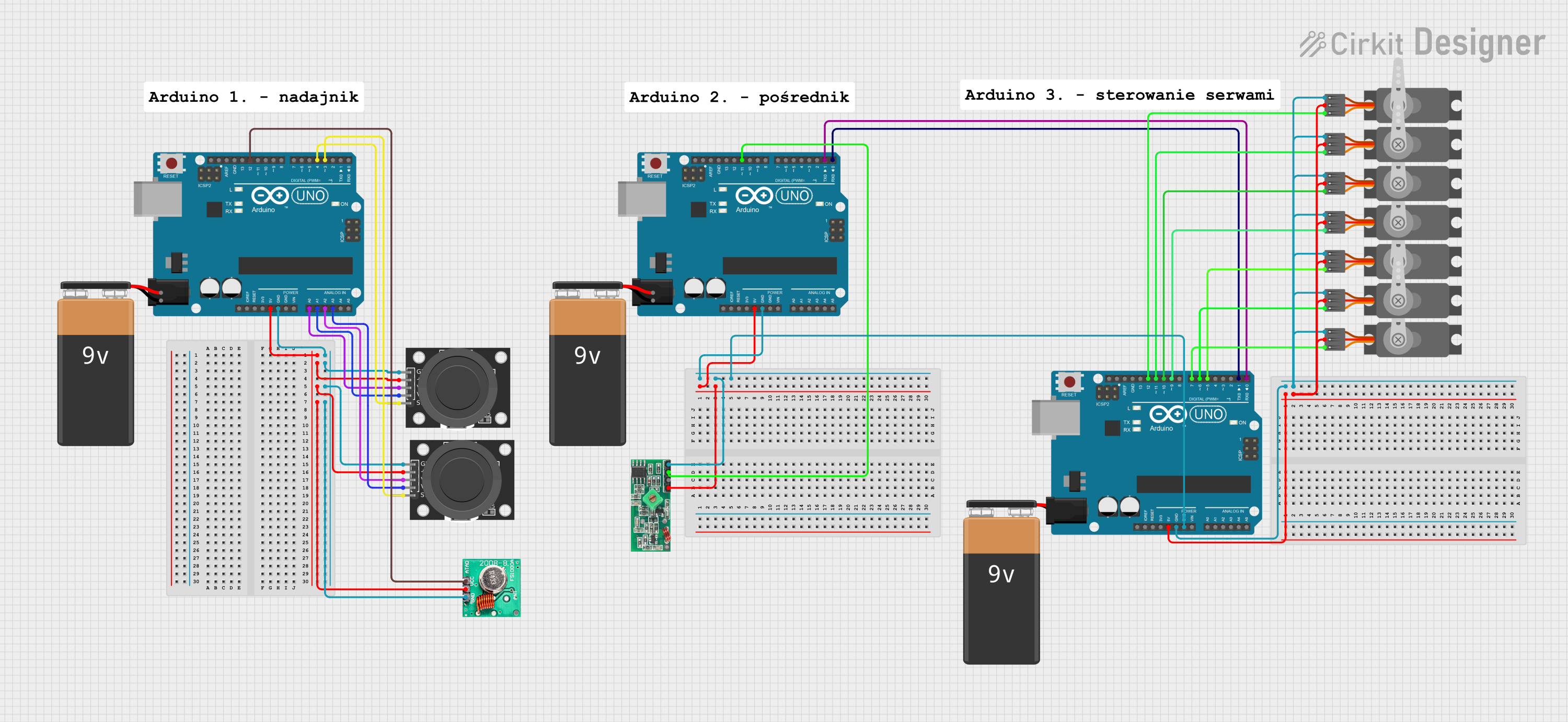
Explore Projects Built with 4 Button RF transmitter remote
Technical Specifications
- Frequency: 315 MHz or 433 MHz (varies by model)
- Operating Voltage: 12V (powered by a 12V A23 battery)
- Transmission Range: Up to 50 meters (in open space, without obstructions)
- Modulation Type: Amplitude Shift Keying (ASK)
- Number of Buttons: 4
- Dimensions: Approximately 60mm x 30mm x 12mm
- Material: Durable plastic casing
Pin Configuration and Descriptions
The 4 Button RF Transmitter Remote does not have traditional pins like ICs or modules. Instead, it transmits signals wirelessly. However, the buttons correspond to specific encoded signals, which are decoded by the receiver. Below is a table describing the button functionality:
| Button | Function |
|---|---|
| Button 1 | Sends Signal 1 (e.g., Turn ON Device 1) |
| Button 2 | Sends Signal 2 (e.g., Turn OFF Device 1) |
| Button 3 | Sends Signal 3 (e.g., Turn ON Device 2) |
| Button 4 | Sends Signal 4 (e.g., Turn OFF Device 2) |
Usage Instructions
How to Use the Component in a Circuit
Pairing with an RF Receiver:
- Ensure the RF receiver module is compatible with the transmitter's frequency (315 MHz or 433 MHz).
- Connect the RF receiver module to your circuit or microcontroller (e.g., Arduino UNO).
- Program the receiver to recognize the unique signals sent by each button.
Powering the Remote:
- Insert a 12V A23 battery into the remote's battery compartment.
- Ensure the battery is installed with the correct polarity.
Testing the Remote:
- Press any button on the remote. The corresponding signal should be transmitted and received by the RF receiver.
- Verify the receiver's output to ensure proper functionality.
Important Considerations and Best Practices
- Range Limitations: The transmission range may be reduced by physical obstructions, interference, or environmental factors. For optimal performance, use the remote in open spaces or minimize obstacles between the transmitter and receiver.
- Battery Maintenance: Replace the battery when the transmission range decreases or the remote becomes unresponsive.
- Interference: Avoid using the remote near devices operating on the same frequency to prevent signal interference.
Example: Using with an Arduino UNO
Below is an example of how to use the 4 Button RF Transmitter Remote with an RF receiver module and an Arduino UNO to control LEDs:
Required Components:
- 4 Button RF Transmitter Remote
- RF Receiver Module (e.g., 433 MHz)
- Arduino UNO
- 4 LEDs
- 4 Resistors (220Ω)
- Breadboard and jumper wires
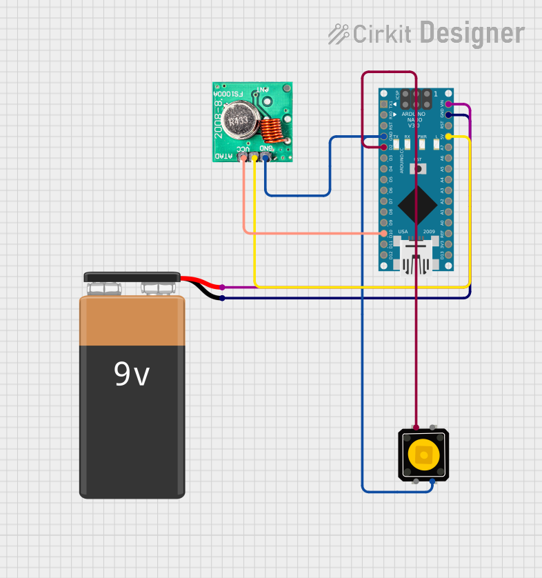
Circuit Diagram:
Connect the RF receiver module to the Arduino UNO as follows:
- VCC: Connect to 5V on the Arduino.
- GND: Connect to GND on the Arduino.
- Data Pin: Connect to digital pin 2 on the Arduino.
Connect the LEDs to digital pins 3, 4, 5, and 6 on the Arduino, each with a 220Ω resistor in series.
Arduino Code:
#include <RCSwitch.h> // Include the RC-Switch library

RCSwitch mySwitch = RCSwitch();

void setup() {
  Serial.begin(9600); // Initialize serial communication
  mySwitch.enableReceive(0); // Receiver on interrupt 0 (pin 2 on Arduino)

  // Set LED pins as output
  pinMode(3, OUTPUT);
  pinMode(4, OUTPUT);
  pinMode(5, OUTPUT);
  pinMode(6, OUTPUT);
}

void loop() {
  if (mySwitch.available()) {
    int receivedValue = mySwitch.getReceivedValue();

    // Check received signal and control LEDs
    if (receivedValue == 12345) { // Replace with actual signal for Button 1
      digitalWrite(3, HIGH); // Turn ON LED 1
    } else if (receivedValue == 23456) { // Replace with actual signal for Button 2
      digitalWrite(3, LOW); // Turn OFF LED 1
    } else if (receivedValue == 34567) { // Replace with actual signal for Button 3
      digitalWrite(4, HIGH); // Turn ON LED 2
    } else if (receivedValue == 45678) { // Replace with actual signal for Button 4
      digitalWrite(4, LOW); // Turn OFF LED 2
    }

    mySwitch.resetAvailable(); // Reset to receive the next signal
  }
}
Note: Replace
12345,23456, etc., with the actual signal values received from your remote. Use the serial monitor to identify these values during testing.
Troubleshooting and FAQs
Common Issues and Solutions
Remote Not Working:
- Ensure the battery is installed correctly and has sufficient charge.
- Verify that the remote and receiver are operating on the same frequency.
Reduced Transmission Range:
- Check for obstructions or interference in the environment.
- Replace the battery if it is weak.
Receiver Not Responding:
- Confirm that the receiver is properly connected to the circuit.
- Ensure the Arduino code is correctly configured to recognize the transmitted signals.
Multiple Devices Interfering:
- If multiple RF devices are operating on the same frequency, consider using a remote with unique encoding or changing the frequency (if supported).
FAQs
Q: Can I use this remote with any RF receiver?
A: The remote must be paired with a receiver operating on the same frequency (315 MHz or 433 MHz) and compatible with the remote's encoding scheme.Q: How do I know the signal values for each button?
A: Use an RF receiver module and a microcontroller (e.g., Arduino) to read and display the signal values on a serial monitor.Q: Can I extend the transmission range?
A: While the range is limited by design, using a high-gain antenna on the receiver may improve performance in some cases.