Cirkit Designer Logo
Cirkit Designer
Your all-in-one circuit design IDE
Home / 
Component Documentation

How to Use LilyGo T-Display RP2040: Examples, Pinouts, and Specs

Image of LilyGo T-Display RP2040
Cirkit Designer LogoDesign with LilyGo T-Display RP2040 in Cirkit Designer

Introduction

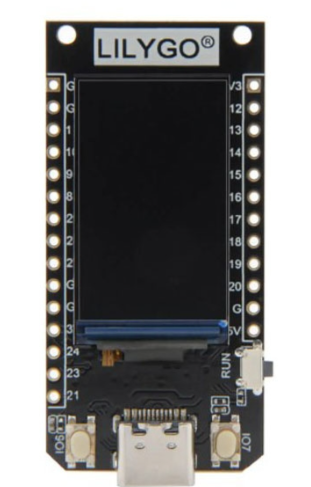
The LilyGo T-Display RP2040 is a versatile development board designed by Xinyuan-LilyGO. It features the RP2040 microcontroller and an integrated 1.14-inch color display, making it an excellent choice for IoT and embedded projects. This board combines the power of the RP2040 with a vibrant display, enabling developers to create visually appealing and interactive applications.

Explore Projects Built with LilyGo T-Display RP2040

Use Cirkit Designer to design, explore, and prototype these projects online. Some projects support real-time simulation. Click "Open Project" to start designing instantly!
Lilygo 7670e-Based Smart Interface with LCD Display and Keypad
Image of Paower: A project utilizing LilyGo T-Display RP2040 in a practical application
This circuit features a Lilygo 7670e microcontroller interfaced with a 16x2 I2C LCD for display, a 4X4 membrane matrix keypad for input, and an arcade button for additional control. It also includes a 4G antenna and a GPS antenna for communication and location tracking capabilities.
Cirkit Designer LogoOpen Project in Cirkit Designer
RTL8720DN-Based Interactive Button-Controlled TFT Display
Image of coba-coba: A project utilizing LilyGo T-Display RP2040 in a practical application
This circuit features an RTL8720DN microcontroller interfaced with a China ST7735S 160x128 TFT LCD display and four pushbuttons. The microcontroller reads the states of the pushbuttons and displays their statuses on the TFT LCD, providing a visual feedback system for button presses.
Cirkit Designer LogoOpen Project in Cirkit Designer
ESP32 Mini-Based Smart Timekeeper with OLED Display and Battery Charging
Image of RM Gloves: A project utilizing LilyGo T-Display RP2040 in a practical application
This circuit features an ESP32 Mini microcontroller as its core, interfaced with a 0.96" OLED display and a DS3231 Real-Time Clock (RTC) for timekeeping and display purposes. A TP4056 module is used for charging a LiPoly battery, which powers the system through an LM2596 voltage regulator and an AMS1117-3.3 voltage regulator to step down and stabilize the voltage for the ESP32 and peripherals. User inputs are captured through a rotary potentiometer and a red pushbutton, which are connected to the ESP32's GPIOs for control and reset functionality.
Cirkit Designer LogoOpen Project in Cirkit Designer
ESP32 Mini Battery-Powered OLED Display with RTC and Potentiometer Control
Image of copy ulit nya: A project utilizing LilyGo T-Display RP2040 in a practical application
This circuit is a battery-powered IoT device featuring an ESP32 microcontroller, an OLED display, and an RTC module for timekeeping. It includes a TP4056 for battery charging, a potentiometer for user input, and a pushbutton for resetting the ESP32. The circuit is designed to display information on the OLED and maintain accurate time using the RTC, with power management handled by the TP4056 and voltage regulation by the LM2596 and AMS1117.
Cirkit Designer LogoOpen Project in Cirkit Designer

Explore Projects Built with LilyGo T-Display RP2040

Use Cirkit Designer to design, explore, and prototype these projects online. Some projects support real-time simulation. Click "Open Project" to start designing instantly!
Image of Paower: A project utilizing LilyGo T-Display RP2040 in a practical application
Lilygo 7670e-Based Smart Interface with LCD Display and Keypad
This circuit features a Lilygo 7670e microcontroller interfaced with a 16x2 I2C LCD for display, a 4X4 membrane matrix keypad for input, and an arcade button for additional control. It also includes a 4G antenna and a GPS antenna for communication and location tracking capabilities.
Cirkit Designer LogoOpen Project in Cirkit Designer
Image of coba-coba: A project utilizing LilyGo T-Display RP2040 in a practical application
RTL8720DN-Based Interactive Button-Controlled TFT Display
This circuit features an RTL8720DN microcontroller interfaced with a China ST7735S 160x128 TFT LCD display and four pushbuttons. The microcontroller reads the states of the pushbuttons and displays their statuses on the TFT LCD, providing a visual feedback system for button presses.
Cirkit Designer LogoOpen Project in Cirkit Designer
Image of RM Gloves: A project utilizing LilyGo T-Display RP2040 in a practical application
ESP32 Mini-Based Smart Timekeeper with OLED Display and Battery Charging
This circuit features an ESP32 Mini microcontroller as its core, interfaced with a 0.96" OLED display and a DS3231 Real-Time Clock (RTC) for timekeeping and display purposes. A TP4056 module is used for charging a LiPoly battery, which powers the system through an LM2596 voltage regulator and an AMS1117-3.3 voltage regulator to step down and stabilize the voltage for the ESP32 and peripherals. User inputs are captured through a rotary potentiometer and a red pushbutton, which are connected to the ESP32's GPIOs for control and reset functionality.
Cirkit Designer LogoOpen Project in Cirkit Designer
Image of copy ulit nya: A project utilizing LilyGo T-Display RP2040 in a practical application
ESP32 Mini Battery-Powered OLED Display with RTC and Potentiometer Control
This circuit is a battery-powered IoT device featuring an ESP32 microcontroller, an OLED display, and an RTC module for timekeeping. It includes a TP4056 for battery charging, a potentiometer for user input, and a pushbutton for resetting the ESP32. The circuit is designed to display information on the OLED and maintain accurate time using the RTC, with power management handled by the TP4056 and voltage regulation by the LM2596 and AMS1117.
Cirkit Designer LogoOpen Project in Cirkit Designer

Common Applications and Use Cases

  • IoT Devices: Ideal for creating smart home devices, environmental monitoring systems, and other IoT applications.
  • Wearable Technology: Suitable for developing wearable gadgets with display capabilities.
  • Prototyping and Development: Perfect for rapid prototyping and development of embedded systems.
  • Educational Projects: Great for learning and teaching microcontroller programming and electronics.

Technical Specifications

Key Technical Details

Specification Value
Microcontroller RP2040
Flash Memory 4MB
Display 1.14-inch color TFT LCD
Resolution 240 x 135 pixels
Operating Voltage 3.3V
Input Voltage 5V (via USB-C)
GPIO Pins 26
Communication Protocols I2C, SPI, UART
Dimensions 51mm x 25mm

Pin Configuration and Descriptions

Pin Number Pin Name Description
1 3V3 3.3V Power Supply
2 GND Ground
3 GP0 General Purpose I/O
4 GP1 General Purpose I/O
5 GP2 General Purpose I/O
6 GP3 General Purpose I/O
7 GP4 General Purpose I/O
8 GP5 General Purpose I/O
9 GP6 General Purpose I/O
10 GP7 General Purpose I/O
11 GP8 General Purpose I/O
12 GP9 General Purpose I/O
13 GP10 General Purpose I/O
14 GP11 General Purpose I/O
15 GP12 General Purpose I/O
16 GP13 General Purpose I/O
17 GP14 General Purpose I/O
18 GP15 General Purpose I/O
19 GP16 General Purpose I/O
20 GP17 General Purpose I/O
21 GP18 General Purpose I/O
22 GP19 General Purpose I/O
23 GP20 General Purpose I/O
24 GP21 General Purpose I/O
25 GP22 General Purpose I/O
26 GP23 General Purpose I/O

Usage Instructions

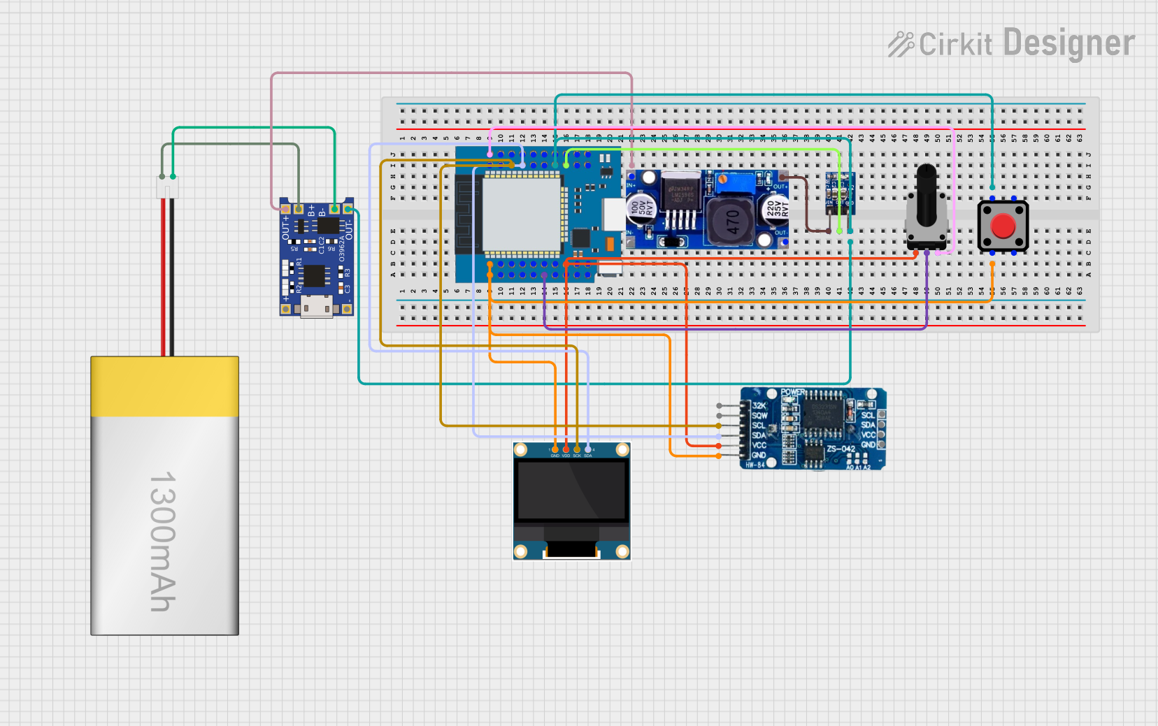
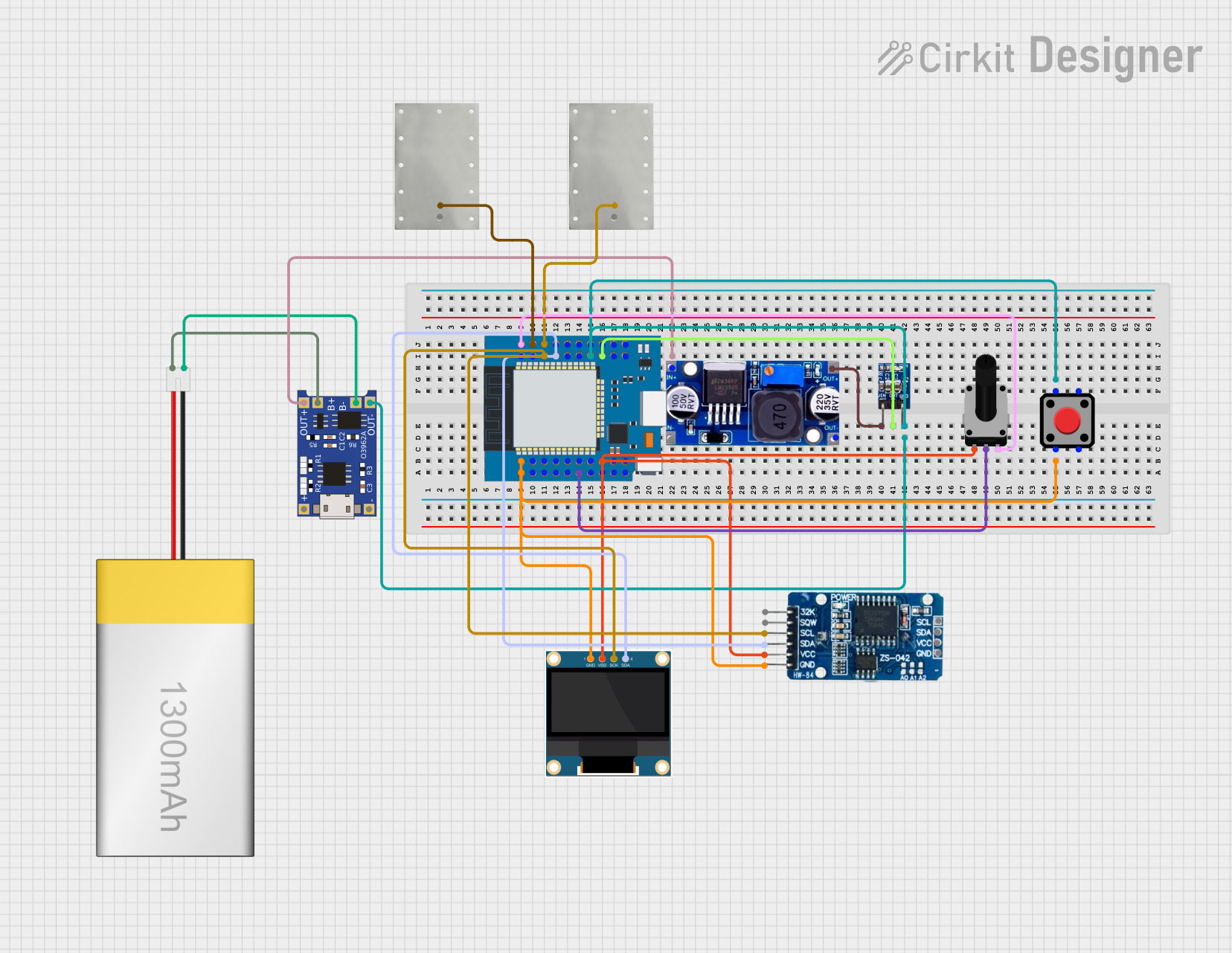
How to Use the Component in a Circuit

  1. Powering the Board:

    • Connect the board to a 5V power source using the USB-C connector.
    • Ensure the power supply provides sufficient current for the board and any connected peripherals.
  2. Connecting to GPIO Pins:

    • Use the GPIO pins for interfacing with sensors, actuators, and other components.
    • Refer to the pin configuration table for the specific pin functions.
  3. Programming the Board:

    • The board can be programmed using the Arduino IDE or MicroPython.
    • Install the necessary board support packages and libraries for the RP2040.

Important Considerations and Best Practices

  • Voltage Levels: Ensure that all connected components operate at 3.3V logic levels to avoid damaging the board.
  • Pin Usage: Avoid using the same GPIO pin for multiple functions simultaneously.
  • Display Handling: Use appropriate libraries to control the integrated display effectively.

Example Code for Arduino IDE

#include <TFT_eSPI.h>  // Include the graphics library

TFT_eSPI tft = TFT_eSPI();  // Create an instance of the display

void setup() {
  tft.init();  // Initialize the display
  tft.setRotation(1);  // Set display orientation
  tft.fillScreen(TFT_BLACK);  // Clear the display
  tft.setTextColor(TFT_WHITE);  // Set text color
  tft.setTextSize(2);  // Set text size
  tft.setCursor(10, 10);  // Set cursor position
  tft.println("Hello, World!");  // Print text to the display
}

void loop() {
  // Add your main code here
}

Troubleshooting and FAQs

Common Issues Users Might Face

  1. Display Not Working:

    • Ensure the display is properly connected and initialized in the code.
    • Check the power supply and connections.
  2. Board Not Recognized by Computer:

    • Verify the USB cable and port are functioning correctly.
    • Ensure the necessary drivers are installed.
  3. GPIO Pins Not Responding:

    • Check for correct pin assignments in the code.
    • Ensure there are no short circuits or loose connections.

Solutions and Tips for Troubleshooting

  • Check Connections: Double-check all connections and ensure they are secure.
  • Update Libraries: Ensure you have the latest versions of the required libraries.
  • Consult Documentation: Refer to the official documentation and community forums for additional support.

By following this documentation, you should be able to effectively utilize the LilyGo T-Display RP2040 in your projects. Whether you are a beginner or an experienced developer, this versatile board offers a wide range of possibilities for your IoT and embedded applications.