
How to Use Adafruit MAX31865 RTD Sensor Breakout: Examples, Pinouts, and Specs
 Design with Adafruit MAX31865 RTD Sensor Breakout in Cirkit Designer
Introduction
The Adafruit MAX31865 RTD Sensor Breakout (Part ID: 3328) is a precision temperature sensor interface designed to work with RTD (Resistance Temperature Detector) sensors, such as PT100 and PT1000. This breakout board leverages the MAX31865 IC to provide accurate temperature measurements by converting the resistance of the RTD into a digital signal. It is ideal for applications requiring precise temperature monitoring, such as industrial automation, scientific experiments, and environmental monitoring.
Explore Projects Built with Adafruit MAX31865 RTD Sensor Breakout
 Open Project in Cirkit Designer
 Open Project in Cirkit Designer
 Open Project in Cirkit Designer
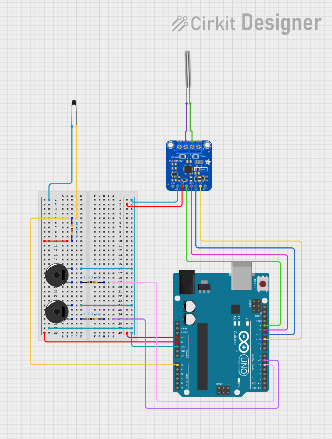 Open Project in Cirkit Designer
Explore Projects Built with Adafruit MAX31865 RTD Sensor Breakout
Open Project in Cirkit DesignerOpen Project in Cirkit DesignerOpen Project in Cirkit DesignerOpen Project in Cirkit DesignerCommon Applications
- Industrial temperature monitoring
- Scientific instrumentation
- HVAC systems
- Environmental data logging
- Precision thermal control systems
Technical Specifications
The Adafruit MAX31865 RTD Sensor Breakout is designed to simplify the integration of RTD sensors into microcontroller-based systems. Below are the key technical details:
General Specifications
| Parameter | Value |
|---|---|
| Supported RTD Types | PT100, PT1000 |
| RTD Measurement Range | -200°C to +850°C |
| Communication Interface | SPI |
| Operating Voltage | 3.3V or 5V |
| Operating Current | ~5mA |
| Dimensions | 25mm x 25mm x 4mm |
| Mounting | 4 x 0.1" mounting holes |
Pin Configuration
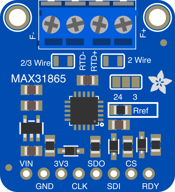
The breakout board features a 7-pin header for SPI communication and power, as well as screw terminals for connecting the RTD sensor. Below is the pinout:
Header Pinout
| Pin Name | Description |
|---|---|
| VIN | Power input (3.3V or 5V) |
| GND | Ground |
| SCK | SPI Clock |
| SDI | SPI Data In (MOSI) |
| SDO | SPI Data Out (MISO) |
| CS | Chip Select (Active Low) |
| DRDY | Data Ready (Optional, Interrupt Output) |
RTD Screw Terminal Pinout
| Terminal | Description |
|---|---|
| RTD+ | Positive terminal of the RTD sensor |
| RTD- | Negative terminal of the RTD sensor |
| F+ | Force+ (used for 4-wire RTD sensors) |
| F- | Force- (used for 4-wire RTD sensors) |
Usage Instructions
Connecting the MAX31865 Breakout
- Power the Breakout Board: Connect the VIN pin to a 3.3V or 5V power source and GND to ground.
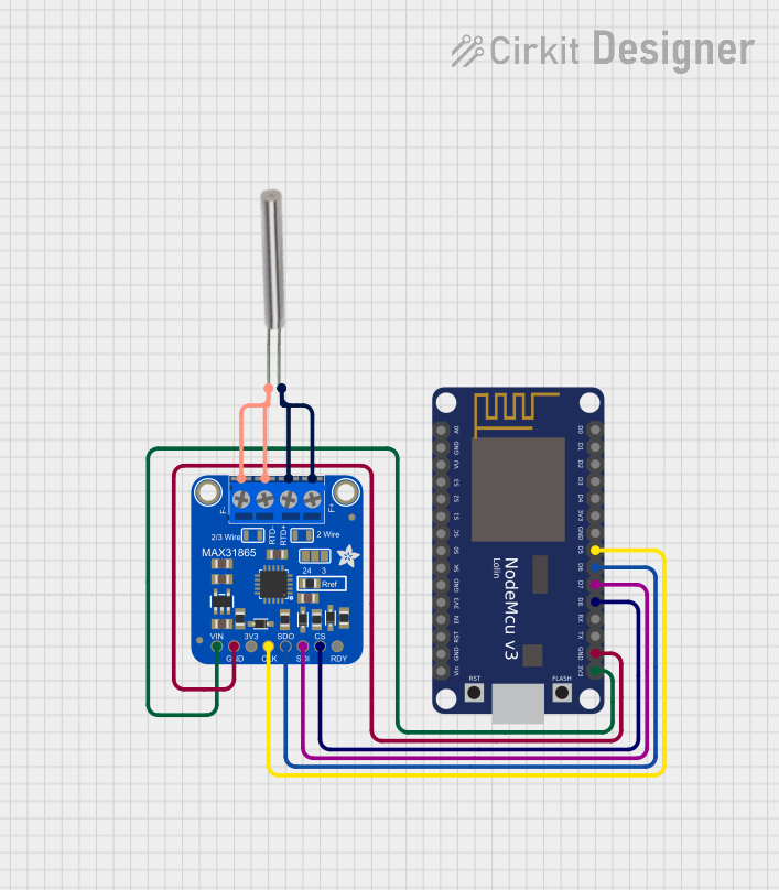
- Connect the RTD Sensor:
- For 2-wire RTD sensors, connect the RTD+ and RTD- terminals.
- For 3-wire RTD sensors, connect RTD+ to one lead, and RTD- to the other two leads.
- For 4-wire RTD sensors, connect RTD+, RTD-, F+, and F- to the corresponding leads.
- Connect to a Microcontroller:
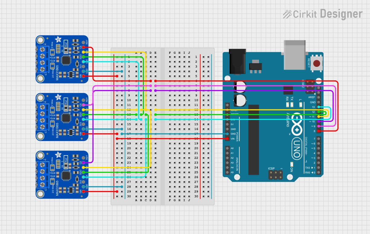
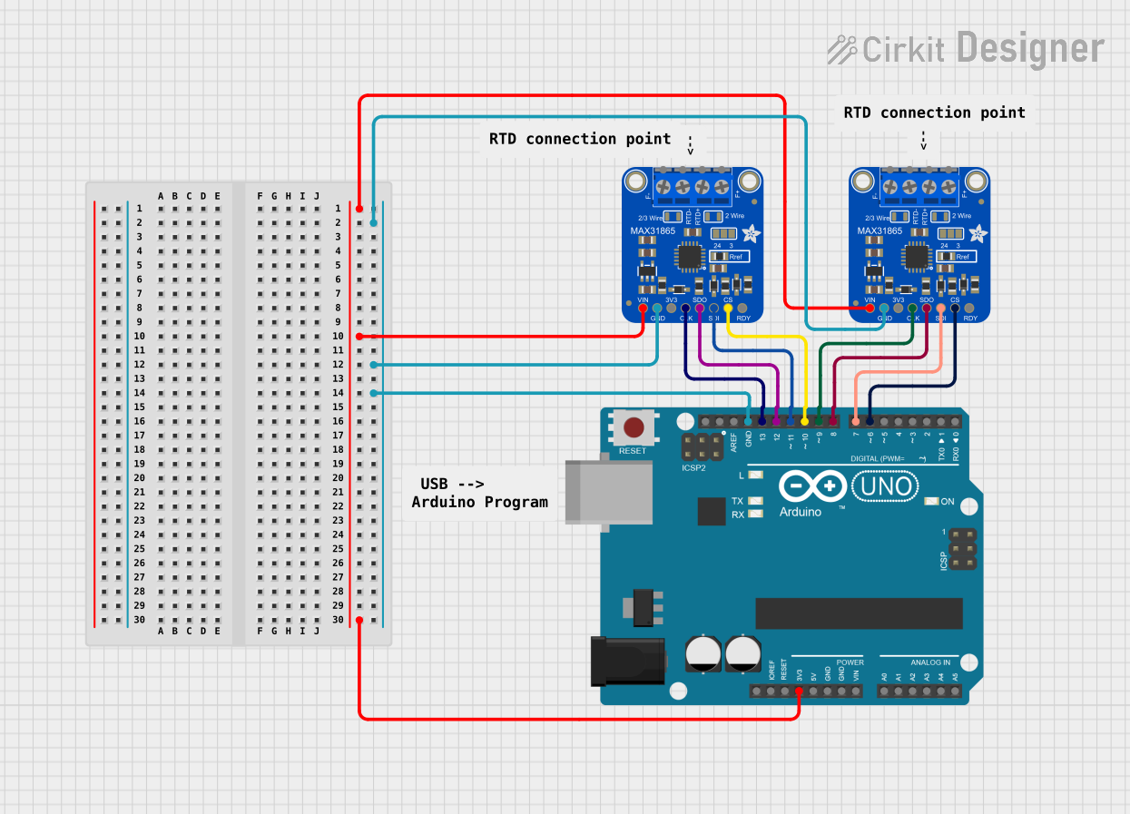
- Use the SPI pins (SCK, SDI, SDO, CS) to interface with your microcontroller.
- Optionally, connect the DRDY pin to an interrupt-capable GPIO pin for data-ready notifications.
Example Arduino UNO Code
Below is an example of how to use the MAX31865 breakout with an Arduino UNO and a PT100 RTD sensor. This example uses the Adafruit MAX31865 library, which can be installed via the Arduino Library Manager.
#include <Adafruit_MAX31865.h>

// Define SPI pins for the MAX31865 breakout
#define MAX31865_CS   10  // Chip Select pin
#define MAX31865_MOSI 11  // SPI MOSI pin
#define MAX31865_MISO 12  // SPI MISO pin
#define MAX31865_SCK  13  // SPI Clock pin

// Create an instance of the MAX31865 class
// Parameters: CS pin, RTD type (PT100 or PT1000)
Adafruit_MAX31865 max31865(MAX31865_CS);

// Uncomment the following line for PT1000 sensors
// #define RTD_TYPE MAX31865_PT1000

void setup() {
  Serial.begin(9600);
  while (!Serial);  // Wait for Serial Monitor to open

  // Initialize the MAX31865 sensor
  if (!max31865.begin(MAX31865_3WIRE)) {
    // MAX31865_3WIRE is for 3-wire RTD sensors; use MAX31865_2WIRE or
    // MAX31865_4WIRE for other configurations.
    Serial.println("Failed to initialize MAX31865!");
    while (1);
  }
  Serial.println("MAX31865 initialized successfully.");
}

void loop() {
  // Read the RTD temperature in Celsius
  float temperature = max31865.temperature(100.0, 430.0);
  // The parameters (100.0, 430.0) are the nominal resistance and reference
  // resistor value for a PT100 sensor. Adjust for PT1000 if needed.

  Serial.print("Temperature: ");
  Serial.print(temperature);
  Serial.println(" °C");

  delay(1000);  // Wait 1 second before the next reading
}
Best Practices
- Use shielded cables for RTD connections to minimize noise interference.
- Ensure proper grounding to avoid measurement errors.
- For long cable runs, consider using 3-wire or 4-wire RTD sensors for better accuracy.
- Use a stable power supply to ensure consistent readings.
Troubleshooting and FAQs
Common Issues
No Temperature Reading:
- Ensure the RTD sensor is properly connected to the screw terminals.
- Verify that the SPI connections between the breakout board and microcontroller are correct.
- Check the power supply voltage (3.3V or 5V).
Inaccurate Temperature Measurements:
- Confirm the RTD type (PT100 or PT1000) and configure the library accordingly.
- Verify the reference resistor value (default is 430Ω for PT100 sensors).
- Minimize electrical noise by using shielded cables and proper grounding.
Communication Errors:
- Ensure the SPI pins are correctly defined in your code.
- Check for loose or faulty connections on the SPI lines.
FAQs
Q: Can I use this breakout with a 2-wire RTD sensor?
A: Yes, the MAX31865 supports 2-wire, 3-wire, and 4-wire RTD sensors. However, 2-wire sensors are less accurate due to lead resistance.
Q: What is the default reference resistor value on the breakout?
A: The default reference resistor value is 430Ω, optimized for PT100 sensors. For PT1000 sensors, you may need to replace the resistor.
Q: Can I use this breakout with a 5V microcontroller?
A: Yes, the breakout is compatible with both 3.3V and 5V logic levels.
Q: How do I calibrate the sensor?
A: Calibration is typically not required for standard RTD sensors. However, you can adjust the nominal resistance and reference resistor values in the library for custom setups.
By following this documentation, you can effectively integrate the Adafruit MAX31865 RTD Sensor Breakout into your projects for precise temperature measurements.