How to Use DC to AC: Examples, Pinouts, and Specs
Introduction
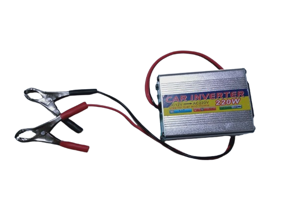
A DC to AC converter is an electronic device that transforms direct current (DC) electricity into alternating current (AC) electricity. This conversion is essential for powering AC devices and appliances using DC power sources, such as batteries or solar panels. DC to AC converters are commonly found in power inverters for renewable energy systems, uninterruptible power supplies (UPS), and portable power stations.
Explore Projects Built with DC to AC


Explore Projects Built with DC to AC
Common Applications and Use Cases
- Solar energy systems: Converting DC from solar panels or batteries to AC for household appliances.
- Uninterruptible power supplies (UPS): Providing backup AC power during outages.
- Electric vehicles: Powering AC components from the DC battery system.
- Portable power stations: Supplying AC power for outdoor or emergency use.
- Industrial and commercial applications: Operating AC equipment from DC power sources.
Technical Specifications
Below are the general technical specifications for a typical DC to AC converter. Note that actual values may vary depending on the specific model or manufacturer.
Key Technical Details
- Input Voltage (DC): 12V, 24V, or 48V (common ranges)
- Output Voltage (AC): 110V or 220V RMS (depending on region)
- Output Frequency: 50Hz or 60Hz
- Output Waveform: Pure sine wave, modified sine wave, or square wave
- Efficiency: 85% to 95% (typical)
- Power Rating: 100W to several kilowatts
- Protection Features: Overload, short circuit, over-temperature, and low/high voltage protection
Pin Configuration and Descriptions
The pin configuration for a DC to AC converter typically includes input and output terminals. Below is a table describing the connections:
| Pin/Terminal | Description |
|---|---|
| DC+ | Positive DC input terminal (connect to the positive terminal of the DC source). |
| DC- | Negative DC input terminal (connect to the negative terminal of the DC source). |
| AC-L | Live AC output terminal (provides the AC live line). |
| AC-N | Neutral AC output terminal (provides the AC neutral line). |
| Ground (GND) | Ground terminal for safety and proper operation. |
Usage Instructions
How to Use the Component in a Circuit
Connect the DC Input:
- Ensure the DC source (e.g., battery or solar panel) matches the input voltage rating of the converter.
- Connect the positive terminal of the DC source to the
DC+pin and the negative terminal to theDC-pin.
Connect the AC Output:
- Connect the
AC-LandAC-Nterminals to the AC load (e.g., an appliance or device). - If required, connect the ground terminal to the earth ground for safety.
- Connect the
Power On:
- Turn on the DC power source. The converter will begin generating AC output.
Monitor Operation:
- Use an appropriate measuring device (e.g., a multimeter) to verify the output voltage and frequency.
Important Considerations and Best Practices
- Match Voltage Ratings: Ensure the input voltage matches the converter's specifications to avoid damage.
- Load Capacity: Do not exceed the power rating of the converter. Overloading can cause overheating or failure.
- Waveform Type: Use a pure sine wave converter for sensitive electronics, as modified or square wave outputs may cause interference or damage.
- Cooling: Ensure proper ventilation or cooling to prevent overheating during operation.
- Safety: Always follow proper grounding practices and avoid touching live terminals.
Example: Connecting a DC to AC Converter to an Arduino UNO
While DC to AC converters are not directly controlled by an Arduino, you can use an Arduino to monitor or control the DC input or AC output indirectly. Below is an example of using an Arduino to monitor the DC input voltage:
// Example: Monitoring DC input voltage of a DC to AC converter
// Connect the DC+ terminal to an analog pin on the Arduino via a voltage divider
// Ensure the voltage divider scales the input voltage to within 0-5V for the Arduino

const int voltagePin = A0; // Analog pin connected to the voltage divider
float inputVoltage = 0.0;  // Variable to store the calculated input voltage

void setup() {
  Serial.begin(9600); // Initialize serial communication
}

void loop() {
  int sensorValue = analogRead(voltagePin); // Read the analog input
  inputVoltage = (sensorValue / 1023.0) * 5.0 * (voltageDividerRatio);
  // Replace 'voltageDividerRatio' with the actual ratio of your voltage divider

  Serial.print("Input Voltage: ");
  Serial.print(inputVoltage);
  Serial.println(" V");

  delay(1000); // Wait for 1 second before the next reading
}
Note: Use a voltage divider to scale down the DC input voltage to a safe range for the Arduino's analog input pins.
Troubleshooting and FAQs
Common Issues and Solutions
No AC Output:
- Cause: Incorrect DC input voltage or loose connections.
- Solution: Verify the DC input voltage and ensure all connections are secure.
Overheating:
- Cause: Overloading or insufficient cooling.
- Solution: Reduce the load or improve ventilation around the converter.
Appliance Not Working Properly:
- Cause: Incompatible output waveform (e.g., modified sine wave instead of pure sine wave).
- Solution: Use a pure sine wave converter for sensitive devices.
Frequent Shutdowns:
- Cause: Low input voltage or over-temperature protection.
- Solution: Check the DC source voltage and ensure proper cooling.
FAQs
Q: Can I use a DC to AC converter with a car battery?
- A: Yes, as long as the converter's input voltage matches the car battery voltage (typically 12V).
Q: What is the difference between pure sine wave and modified sine wave output?
- A: Pure sine wave output closely mimics the AC power from the grid, making it suitable for all devices. Modified sine wave output is less smooth and may cause issues with sensitive electronics.
Q: How do I calculate the required power rating for my converter?
- A: Add up the power ratings (in watts) of all connected devices and choose a converter with a power rating at least 20-30% higher than the total.
Q: Can I connect multiple DC sources to a single converter?
- A: Yes, but ensure the sources are properly configured (e.g., in parallel) and their combined voltage matches the converter's input rating.