
How to Use nrf24l01+pa+lna: Examples, Pinouts, and Specs
 Design with nrf24l01+pa+lna in Cirkit Designer
Introduction
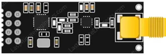
The nRF24L01+PA+LNA, manufactured by Nordic Semiconductor ASA, is a low-power 2.4GHz transceiver module designed for wireless communication. It features an integrated Power Amplifier (PA) and Low-Noise Amplifier (LNA), which significantly enhance its transmission range and sensitivity compared to the standard nRF24L01 module. This module is widely used in applications requiring reliable, long-range, and low-power wireless communication.
Explore Projects Built with nrf24l01+pa+lna
 Open Project in Cirkit Designer
 Open Project in Cirkit Designer
 Open Project in Cirkit Designer
 Open Project in Cirkit Designer
Explore Projects Built with nrf24l01+pa+lna
Open Project in Cirkit DesignerOpen Project in Cirkit DesignerOpen Project in Cirkit DesignerOpen Project in Cirkit DesignerCommon Applications
- Wireless sensor networks
- Remote controls (e.g., drones, RC cars)
- Home automation systems
- Industrial monitoring and control
- Internet of Things (IoT) devices
Technical Specifications
Below are the key technical details of the nRF24L01+PA+LNA module:
| Parameter | Value |
|---|---|
| Operating Frequency | 2.4GHz ISM Band |
| Modulation | GFSK (Gaussian Frequency Shift Keying) |
| Data Rate | 250kbps, 1Mbps, 2Mbps |
| Operating Voltage | 1.9V to 3.6V |
| Maximum Output Power | +20dBm |
| Sensitivity | -94dBm at 1Mbps |
| Communication Range | Up to 1,000 meters (line of sight) |
| Current Consumption (TX) | ~115mA at maximum power |
| Current Consumption (RX) | ~13.5mA |
| Standby Current | ~26µA |
| Interface | SPI (Serial Peripheral Interface) |
| Antenna | External SMA antenna |
Pin Configuration
The nRF24L01+PA+LNA module typically has an 8-pin interface. Below is the pinout description:
| Pin | Name | Description |
|---|---|---|
| 1 | GND | Ground connection |
| 2 | VCC | Power supply (3.3V recommended) |
| 3 | CE | Chip Enable: Activates RX or TX mode |
| 4 | CSN | Chip Select Not: SPI enable (active low) |
| 5 | SCK | Serial Clock: SPI clock input |
| 6 | MOSI | Master Out Slave In: SPI data input |
| 7 | MISO | Master In Slave Out: SPI data output |
| 8 | IRQ | Interrupt Request: Indicates data received or transmission complete (optional) |
Usage Instructions
How to Use the nRF24L01+PA+LNA in a Circuit
- Power Supply: Connect the VCC pin to a stable 3.3V power source. Avoid using 5V as it may damage the module. Use a decoupling capacitor (e.g., 10µF) between VCC and GND to stabilize the power supply.
- SPI Interface: Connect the SPI pins (CSN, SCK, MOSI, MISO) to the corresponding SPI pins on your microcontroller.
- CE Pin: Use a GPIO pin on your microcontroller to control the CE pin. Set it high to enable RX/TX mode and low for standby mode.
- IRQ Pin: Optionally connect the IRQ pin to a GPIO pin on your microcontroller to handle interrupts for events like data reception or transmission completion.
- Antenna: Attach the external SMA antenna to the module for optimal range and performance.
Best Practices
- Use a dedicated 3.3V regulator to power the module, as it can draw significant current during transmission.
- Keep the module away from high-frequency noise sources to avoid interference.
- Use proper shielding and grounding techniques for reliable operation in noisy environments.
- Ensure the SPI clock speed does not exceed 10MHz for stable communication.
Example Code for Arduino UNO
Below is an example of how to use the nRF24L01+PA+LNA module with an Arduino UNO. This code uses the popular RF24 library.
#include <SPI.h>
#include <nRF24L01.h>
#include <RF24.h>

// Define the CE and CSN pins for the nRF24L01+PA+LNA module
#define CE_PIN 9
#define CSN_PIN 10

// Create an RF24 object
RF24 radio(CE_PIN, CSN_PIN);

// Define the address for communication
const byte address[6] = "00001";

void setup() {
  // Initialize serial communication for debugging
  Serial.begin(9600);

  // Initialize the nRF24L01+PA+LNA module
  radio.begin();

  // Set the communication address
  radio.openWritingPipe(address);

  // Set the module to send data
  radio.setPALevel(RF24_PA_HIGH);

  // Set the data rate to 1Mbps
  radio.setDataRate(RF24_1MBPS);

  // Start the radio in TX mode
  radio.stopListening();

  Serial.println("nRF24L01+PA+LNA initialized and ready to transmit.");
}

void loop() {
  // Define the message to send
  const char text[] = "Hello, world!";

  // Send the message
  bool success = radio.write(&text, sizeof(text));

  // Print the transmission status
  if (success) {
    Serial.println("Message sent successfully!");
  } else {
    Serial.println("Message failed to send.");
  }

  // Wait for 1 second before sending the next message
  delay(1000);
}
Troubleshooting and FAQs
Common Issues
Module Not Responding:
- Ensure the module is powered with a stable 3.3V supply.
- Verify the SPI connections and pin assignments in your code.
- Check for loose or faulty wiring.
Short Communication Range:
- Ensure the external antenna is securely connected.
- Avoid obstructions and interference from other 2.4GHz devices.
- Increase the PA level using the
setPALevel()function in the RF24 library.
Data Transmission Fails:
- Verify that the sender and receiver modules are using the same address and data rate.
- Check the CE and CSN pin configurations in your code.
High Current Draw:
- Use a dedicated 3.3V regulator with sufficient current capacity.
- Add decoupling capacitors near the module's power pins.
FAQs
Q: Can I power the module with 5V?
A: No, the nRF24L01+PA+LNA module operates at 3.3V. Using 5V can damage the module. Use a voltage regulator if your microcontroller operates at 5V.
Q: What is the maximum range of the module?
A: The module can achieve up to 1,000 meters of range in line-of-sight conditions with the external antenna.
Q: Do I need to use the IRQ pin?
A: The IRQ pin is optional. It can be used to handle interrupts for events like data reception or transmission completion, but it is not required for basic operation.
Q: Can I use multiple modules in the same network?
A: Yes, the nRF24L01+PA+LNA supports multiple devices in the same network using unique addresses for each module.
By following this documentation, you can effectively integrate the nRF24L01+PA+LNA module into your wireless communication projects.