Cirkit Designer Logo
Cirkit Designer
Your all-in-one circuit design IDE
Home / 
Component Documentation

How to Use VL6180X: Examples, Pinouts, and Specs

Image of VL6180X
Cirkit Designer LogoDesign with VL6180X in Cirkit Designer

Introduction

The VL6180X is a time-of-flight (ToF) distance sensor capable of measuring distances up to 100 mm with high accuracy. It combines an infrared emitter and a photodetector in a compact package, enabling precise proximity sensing and ambient light measurement. This sensor is widely used in robotics, automation, and consumer electronics due to its reliability and ease of integration.

Explore Projects Built with VL6180X

Use Cirkit Designer to design, explore, and prototype these projects online. Some projects support real-time simulation. Click "Open Project" to start designing instantly!
Cellular-Enabled IoT Device with Real-Time Clock and Power Management
Image of LRCM PHASE 2 BASIC: A project utilizing VL6180X in a practical application
This circuit features a LilyGo-SIM7000G module for cellular communication and GPS functionality, interfaced with an RTC DS3231 for real-time clock capabilities. It includes voltage sensing through two voltage sensor modules, and uses an 8-channel opto-coupler for isolating different parts of the circuit. Power management is handled by a buck converter connected to a DC power source and batteries, with a fuse for protection and a rocker switch for on/off control. Additionally, there's an LED for indication purposes.
Cirkit Designer LogoOpen Project in Cirkit Designer
Arduino Nano Based GPS Tracker with GSM Communication and Accelerometer
Image of Circuit Aayush: A project utilizing VL6180X in a practical application
This circuit is designed for communication and location tracking purposes. It features an Arduino Nano interfaced with a SIM800L GSM module for cellular connectivity, a GPS NEO 6M module for obtaining geographical coordinates, and an AITrip ADXL335 GY-61 accelerometer for motion sensing. The LM2596 Step Down Module is used to regulate the power supply to the components.
Cirkit Designer LogoOpen Project in Cirkit Designer
Smart Weighing System with ESP8266 and HX711 - Battery Powered and Wi-Fi Enabled
Image of gggg: A project utilizing VL6180X in a practical application
This circuit is a multi-sensor data acquisition system powered by a 18650 battery and managed by an ESP8266 microcontroller. It includes a load sensor interfaced with an HX711 module for weight measurement, an IR sensor, an ADXL345 accelerometer, a VL53L0X distance sensor, and a Neo 6M GPS module for location tracking. The system is designed for wireless data transmission and is supported by a TP4056 module for battery charging.
Cirkit Designer LogoOpen Project in Cirkit Designer
ESP32-Based Multi-Sensor Health Monitoring System with Bluetooth Connectivity
Image of circuit diagram: A project utilizing VL6180X in a practical application
This circuit features an ESP32-WROOM-32UE microcontroller as the central processing unit, interfacing with a variety of sensors and modules. It includes a MAX30100 pulse oximeter and heart-rate sensor, an MLX90614 infrared thermometer, an HC-05 Bluetooth module for wireless communication, and a Neo 6M GPS module for location tracking. All components are powered by a common voltage supply and are connected to specific GPIO pins on the ESP32 for data exchange, with the sensors using I2C communication and the modules using UART.
Cirkit Designer LogoOpen Project in Cirkit Designer

Explore Projects Built with VL6180X

Use Cirkit Designer to design, explore, and prototype these projects online. Some projects support real-time simulation. Click "Open Project" to start designing instantly!
Image of LRCM PHASE 2 BASIC: A project utilizing VL6180X in a practical application
Cellular-Enabled IoT Device with Real-Time Clock and Power Management
This circuit features a LilyGo-SIM7000G module for cellular communication and GPS functionality, interfaced with an RTC DS3231 for real-time clock capabilities. It includes voltage sensing through two voltage sensor modules, and uses an 8-channel opto-coupler for isolating different parts of the circuit. Power management is handled by a buck converter connected to a DC power source and batteries, with a fuse for protection and a rocker switch for on/off control. Additionally, there's an LED for indication purposes.
Cirkit Designer LogoOpen Project in Cirkit Designer
Image of Circuit Aayush: A project utilizing VL6180X in a practical application
Arduino Nano Based GPS Tracker with GSM Communication and Accelerometer
This circuit is designed for communication and location tracking purposes. It features an Arduino Nano interfaced with a SIM800L GSM module for cellular connectivity, a GPS NEO 6M module for obtaining geographical coordinates, and an AITrip ADXL335 GY-61 accelerometer for motion sensing. The LM2596 Step Down Module is used to regulate the power supply to the components.
Cirkit Designer LogoOpen Project in Cirkit Designer
Image of gggg: A project utilizing VL6180X in a practical application
Smart Weighing System with ESP8266 and HX711 - Battery Powered and Wi-Fi Enabled
This circuit is a multi-sensor data acquisition system powered by a 18650 battery and managed by an ESP8266 microcontroller. It includes a load sensor interfaced with an HX711 module for weight measurement, an IR sensor, an ADXL345 accelerometer, a VL53L0X distance sensor, and a Neo 6M GPS module for location tracking. The system is designed for wireless data transmission and is supported by a TP4056 module for battery charging.
Cirkit Designer LogoOpen Project in Cirkit Designer
Image of circuit diagram: A project utilizing VL6180X in a practical application
ESP32-Based Multi-Sensor Health Monitoring System with Bluetooth Connectivity
This circuit features an ESP32-WROOM-32UE microcontroller as the central processing unit, interfacing with a variety of sensors and modules. It includes a MAX30100 pulse oximeter and heart-rate sensor, an MLX90614 infrared thermometer, an HC-05 Bluetooth module for wireless communication, and a Neo 6M GPS module for location tracking. All components are powered by a common voltage supply and are connected to specific GPIO pins on the ESP32 for data exchange, with the sensors using I2C communication and the modules using UART.
Cirkit Designer LogoOpen Project in Cirkit Designer

Common Applications

  • Obstacle detection in robotics
  • Gesture recognition in consumer devices
  • Automatic lighting control
  • Proximity sensing in industrial automation
  • Object detection in smart appliances

Technical Specifications

The VL6180X is a highly integrated sensor with the following key specifications:

Parameter Value
Operating Voltage 2.6 V to 3.3 V
Communication Interface I²C (Inter-Integrated Circuit)
Distance Measurement Range 0 mm to 100 mm
Ambient Light Sensing Range 0.01 lux to 1000 lux
Current Consumption 1.7 mA (typical during operation)
Infrared Wavelength 850 nm
Operating Temperature Range -20°C to +70°C
Package Dimensions 4.8 mm × 2.8 mm × 1.0 mm

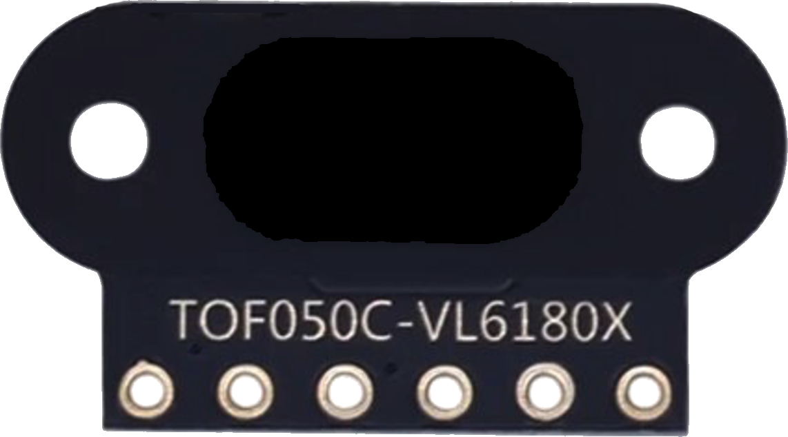
Pin Configuration and Descriptions

The VL6180X has a total of 6 pins. Below is the pinout and description:

Pin Name Pin Number Description
GND 1 Ground connection
VIN 2 Power supply input (2.6 V to 3.3 V)
SCL 3 I²C clock line
SDA 4 I²C data line
GPIO0 5 General-purpose input/output (interrupt output)
GPIO1 6 General-purpose input/output (optional use)

Usage Instructions

How to Use the VL6180X in a Circuit

  1. Power Supply: Connect the VIN pin to a 3.3 V power source and the GND pin to ground.
  2. I²C Communication: Connect the SCL and SDA pins to the corresponding I²C lines of your microcontroller. Use pull-up resistors (typically 4.7 kΩ) on both lines if not already present.
  3. Interrupt Pin: Optionally, connect GPIO0 to a microcontroller pin to handle interrupts for proximity or ambient light events.
  4. Initialization: Use an appropriate library or write custom I²C commands to initialize the sensor and configure its settings.

Important Considerations

  • Voltage Levels: Ensure the I²C lines operate at 3.3 V logic levels. Use a level shifter if your microcontroller operates at 5 V.
  • Distance Limitations: The sensor is optimized for distances up to 100 mm. Beyond this range, accuracy may degrade.
  • Ambient Light: Avoid direct exposure to strong infrared light sources, as they may interfere with measurements.
  • Mounting: Place the sensor in a location where the field of view is unobstructed for accurate readings.

Example Code for Arduino UNO

Below is an example of how to use the VL6180X with an Arduino UNO. This code uses the Adafruit VL6180X library, which simplifies communication with the sensor.

#include <Wire.h>
#include "Adafruit_VL6180X.h"

// Create an instance of the VL6180X sensor
Adafruit_VL6180X vl6180x = Adafruit_VL6180X();

void setup() {
  Serial.begin(9600); // Initialize serial communication
  while (!Serial) {
    delay(10); // Wait for the serial monitor to open
  }

  // Initialize the sensor
  if (!vl6180x.begin()) {
    Serial.println("Failed to find VL6180X sensor! Check wiring.");
    while (1);
  }
  Serial.println("VL6180X sensor initialized.");
}

void loop() {
  // Read the distance in millimeters
  uint8_t distance = vl6180x.readRange();
  uint8_t status = vl6180x.readRangeStatus();

  // Check if the reading is valid
  if (status == VL6180X_ERROR_NONE) {
    Serial.print("Distance: ");
    Serial.print(distance);
    Serial.println(" mm");
  } else {
    Serial.print("Error reading distance: ");
    Serial.println(status);
  }

  delay(500); // Wait 500 ms before the next reading
}

Troubleshooting and FAQs

Common Issues

  1. Sensor Not Detected:

    • Cause: Incorrect I²C wiring or address mismatch.
    • Solution: Verify the SCL and SDA connections. Ensure the I²C address (default: 0x29) matches the one in your code.
  2. Inaccurate Distance Readings:

    • Cause: Obstructions in the sensor's field of view or reflective surfaces.
    • Solution: Ensure the sensor has a clear line of sight and avoid highly reflective objects.
  3. Ambient Light Interference:

    • Cause: Strong infrared light sources nearby.
    • Solution: Shield the sensor from direct sunlight or other IR sources.
  4. High Power Consumption:

    • Cause: Continuous operation without power-saving modes.
    • Solution: Use the sensor's built-in power-saving features when idle.

FAQs

Q1: Can the VL6180X measure distances beyond 100 mm?
A1: The sensor is optimized for distances up to 100 mm. While it may detect objects slightly beyond this range, accuracy is not guaranteed.

Q2: Can I use the VL6180X with a 5 V microcontroller?
A2: Yes, but you must use a level shifter for the I²C lines to prevent damage to the sensor.

Q3: How do I handle multiple VL6180X sensors on the same I²C bus?
A3: Each sensor must have a unique I²C address. This can be achieved by enabling and disabling the sensors sequentially during initialization.

Q4: Does the VL6180X require calibration?
A4: The sensor is factory-calibrated and does not require additional calibration for most applications. However, you can fine-tune settings for specific use cases if needed.