Cirkit Designer Logo
Cirkit Designer
Your all-in-one circuit design IDE
Home / 
Component Documentation

How to Use traic dual channel: Examples, Pinouts, and Specs

Image of traic dual channel
Cirkit Designer LogoDesign with traic dual channel in Cirkit Designer

Introduction

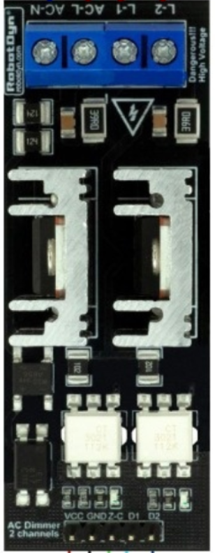
A TRIAC (Triode for Alternating Current) dual channel is a semiconductor device designed for controlling AC power. It is capable of switching and regulating power in both directions, making it highly versatile for alternating current applications. The dual channel feature allows independent control of two separate loads, which is particularly useful in scenarios requiring multi-load management.

Explore Projects Built with traic dual channel

Use Cirkit Designer to design, explore, and prototype these projects online. Some projects support real-time simulation. Click "Open Project" to start designing instantly!
Pushbutton-Controlled Dual LED Circuit with NPN Transistors
Image of transistor pair sr latch: A project utilizing traic dual channel in a practical application
This is a dual-channel pushbutton-controlled LED circuit. Each channel uses a pushbutton to activate an NPN transistor switch, which in turn lights up an LED. The circuit operates on a 5V DC supply.
Cirkit Designer LogoOpen Project in Cirkit Designer
Scarlett 4i4 Audio Loopback Interface
Image of Loopback Interface: A project utilizing traic dual channel in a practical application
The circuit features a Scarlett 4i4 audio interface with no additional components or microcontroller code. It appears to be a simple pass-through or loopback setup, where Line In 1 is directly connected to Line Out 1, and Line In 2 is directly connected to Line Out 2. This could be used for testing the audio interface's throughput or for routing audio signals internally.
Cirkit Designer LogoOpen Project in Cirkit Designer
Dual RTC DS3231 Synchronization with Glyph C3 Microcontroller
Image of DS: A project utilizing traic dual channel in a practical application
This circuit integrates two RTC DS3231 real-time clock modules with a Glyph C3 microcontroller. The RTC modules are connected to the microcontroller via I2C communication protocol, using the SCL and SDA lines for clock and data respectively. Both RTC modules and the microcontroller share a common power supply (3V3) and ground (GND), indicating that they operate at the same voltage level.
Cirkit Designer LogoOpen Project in Cirkit Designer
ESP32-Based Portable Smart Speaker with Audio Input Processing
Image of talkAI: A project utilizing traic dual channel in a practical application
This circuit features two ESP32 microcontrollers configured for serial communication, with one ESP32's TX0 connected to the other's RX2, and vice versa. An INMP441 microphone is interfaced with one ESP32 for audio input, using I2S protocol with connections for serial clock (SCK), word select (WS), and serial data (SD). A Max98357 audio amplifier is connected to the other ESP32 to drive a loudspeaker, receiving I2S data (DIN), bit clock (BLCK), and left-right clock (LRC), and is powered by a lipo battery charger module.
Cirkit Designer LogoOpen Project in Cirkit Designer

Explore Projects Built with traic dual channel

Use Cirkit Designer to design, explore, and prototype these projects online. Some projects support real-time simulation. Click "Open Project" to start designing instantly!
Image of transistor pair sr latch: A project utilizing traic dual channel in a practical application
Pushbutton-Controlled Dual LED Circuit with NPN Transistors
This is a dual-channel pushbutton-controlled LED circuit. Each channel uses a pushbutton to activate an NPN transistor switch, which in turn lights up an LED. The circuit operates on a 5V DC supply.
Cirkit Designer LogoOpen Project in Cirkit Designer
Image of Loopback Interface: A project utilizing traic dual channel in a practical application
Scarlett 4i4 Audio Loopback Interface
The circuit features a Scarlett 4i4 audio interface with no additional components or microcontroller code. It appears to be a simple pass-through or loopback setup, where Line In 1 is directly connected to Line Out 1, and Line In 2 is directly connected to Line Out 2. This could be used for testing the audio interface's throughput or for routing audio signals internally.
Cirkit Designer LogoOpen Project in Cirkit Designer
Image of DS: A project utilizing traic dual channel in a practical application
Dual RTC DS3231 Synchronization with Glyph C3 Microcontroller
This circuit integrates two RTC DS3231 real-time clock modules with a Glyph C3 microcontroller. The RTC modules are connected to the microcontroller via I2C communication protocol, using the SCL and SDA lines for clock and data respectively. Both RTC modules and the microcontroller share a common power supply (3V3) and ground (GND), indicating that they operate at the same voltage level.
Cirkit Designer LogoOpen Project in Cirkit Designer
Image of talkAI: A project utilizing traic dual channel in a practical application
ESP32-Based Portable Smart Speaker with Audio Input Processing
This circuit features two ESP32 microcontrollers configured for serial communication, with one ESP32's TX0 connected to the other's RX2, and vice versa. An INMP441 microphone is interfaced with one ESP32 for audio input, using I2S protocol with connections for serial clock (SCK), word select (WS), and serial data (SD). A Max98357 audio amplifier is connected to the other ESP32 to drive a loudspeaker, receiving I2S data (DIN), bit clock (BLCK), and left-right clock (LRC), and is powered by a lipo battery charger module.
Cirkit Designer LogoOpen Project in Cirkit Designer

Common Applications and Use Cases

  • Light dimmers for residential and commercial lighting systems
  • Motor speed control in fans, pumps, and industrial machinery
  • Heating systems such as electric ovens and water heaters
  • Phase control in AC circuits
  • Home automation systems for controlling multiple devices

Technical Specifications

Below are the key technical details for a typical TRIAC dual channel:

Parameter Value
Maximum Voltage (VDRM) 600V - 800V (varies by model)
Maximum Current (IT) 4A - 16A (per channel)
Gate Trigger Voltage (VGT) 1.5V - 2.5V
Gate Trigger Current (IGT) 10mA - 50mA
Holding Current (IH) 5mA - 25mA
Operating Temperature Range -40°C to +125°C
Isolation Voltage (between channels) 1500V

Pin Configuration and Descriptions

The TRIAC dual channel typically comes in a multi-pin package. Below is an example pinout for a common configuration:

Pin Number Pin Name Description
1 MT1 (Channel 1) Main Terminal 1 for Channel 1
2 MT2 (Channel 1) Main Terminal 2 for Channel 1
3 G1 Gate for Channel 1
4 MT1 (Channel 2) Main Terminal 1 for Channel 2
5 MT2 (Channel 2) Main Terminal 2 for Channel 2
6 G2 Gate for Channel 2

Usage Instructions

How to Use the Component in a Circuit

  1. Power Supply: Ensure the TRIAC is connected to an AC power source within its voltage and current ratings.
  2. Gate Control: Use a low-power control signal (e.g., from a microcontroller or optoisolator) to trigger the gate (G1 or G2) of the desired channel.
  3. Load Connection: Connect the load between MT1 and MT2 of the respective channel. Ensure the load does not exceed the TRIAC's current rating.
  4. Snubber Circuit: For inductive loads (e.g., motors), include a snubber circuit (a resistor-capacitor network) across MT1 and MT2 to prevent voltage spikes.

Important Considerations and Best Practices

  • Heat Dissipation: Use an appropriate heatsink to manage heat generated during operation, especially for high-current loads.
  • Isolation: If controlling the TRIAC with a microcontroller, use an optoisolator to protect the low-voltage control circuit from high-voltage AC.
  • Gate Resistor: Include a resistor in series with the gate to limit the gate current and prevent damage.
  • Zero-Crossing Detection: For smoother operation in light dimming or motor control, consider using a zero-crossing detection circuit.

Example Code for Arduino UNO

Below is an example of how to control one channel of a TRIAC dual channel using an Arduino UNO:

// Define the pin connected to the TRIAC gate
const int triacGatePin = 9; 

void setup() {
  pinMode(triacGatePin, OUTPUT); // Set the TRIAC gate pin as an output
}

void loop() {
  digitalWrite(triacGatePin, HIGH); // Trigger the TRIAC gate
  delay(10); // Keep the gate on for 10ms (adjust as needed)
  digitalWrite(triacGatePin, LOW); // Turn off the gate
  delay(1000); // Wait for 1 second before triggering again
}

Note: The above code assumes a simple on/off control. For phase control (e.g., dimming), you would need to synchronize the gate signal with the AC mains zero-crossing point.

Troubleshooting and FAQs

Common Issues and Solutions

  1. TRIAC Does Not Turn On

    • Cause: Insufficient gate current.
    • Solution: Check the gate resistor value and ensure the control signal provides enough current to trigger the gate.
  2. TRIAC Stays On

    • Cause: Load current is above the holding current threshold.
    • Solution: Ensure the load is within the TRIAC's rated current range.
  3. Excessive Heat

    • Cause: High current load or insufficient cooling.
    • Solution: Use a heatsink and ensure proper ventilation.
  4. Noise or Flickering in Load

    • Cause: Inductive load without a snubber circuit.
    • Solution: Add a snubber circuit across MT1 and MT2.

FAQs

Q: Can I use a TRIAC dual channel for DC loads?
A: No, TRIACs are designed for AC loads. They rely on the alternating nature of AC to turn off (commutate).

Q: How do I control both channels independently?
A: Use separate control signals for G1 and G2. Ensure the control circuit is isolated from the AC side.

Q: What happens if I exceed the maximum voltage or current ratings?
A: Exceeding the ratings can permanently damage the TRIAC or cause it to fail catastrophically. Always operate within the specified limits.

Q: Do I need a heatsink for low-power applications?
A: For low-power loads, a heatsink may not be necessary. However, monitor the TRIAC's temperature during operation to ensure it stays within safe limits.