How to Use VNH5019: Examples, Pinouts, and Specs
Introduction
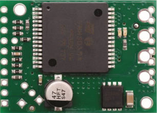
The VNH5019 is a high-current H-bridge motor driver designed to control DC motors in both forward and reverse directions. Manufactured with robust protection features such as overcurrent protection, thermal shutdown, and under-voltage lockout, the VNH5019 is ideal for applications requiring reliable motor control. Its compact design and high current-handling capability make it a popular choice for robotics, industrial automation, and remote-controlled vehicles.
Explore Projects Built with VNH5019


Explore Projects Built with VNH5019
Common Applications
- Robotics and automation systems
- Remote-controlled vehicles
- Conveyor belts and industrial actuators
- Electric wheelchairs and mobility devices
- General-purpose DC motor control
Technical Specifications
The VNH5019 motor driver is designed to handle high currents and voltages while providing precise motor control. Below are its key technical specifications:
| Parameter | Value |
|---|---|
| Operating Voltage Range | 5.5V to 24V |
| Maximum Continuous Current | 12A |
| Peak Current (for short time) | 30A |
| Logic Input Voltage Range | 3V to 5.5V |
| PWM Frequency | Up to 20 kHz |
| Standby Current | < 10 µA |
| Thermal Shutdown Threshold | 170°C (typical) |
| Overcurrent Protection | Yes |
| Under-voltage Lockout | Yes |
| Package Type | MultiPowerSO-30 |
Pin Configuration and Descriptions
The VNH5019 has 30 pins, with key pins used for motor control and power connections. Below is a summary of the most important pins:
| Pin Name | Pin Number | Description |
|---|---|---|
| VIN | 1 | Motor power supply input (5.5V to 24V). |
| GND | 2, 15, 30 | Ground connection. |
| INA | 3 | Input A: Controls motor direction (logic high or low). |
| INB | 4 | Input B: Controls motor direction (logic high or low). |
| PWM | 5 | Pulse Width Modulation input for speed control. |
| EN/DIAG | 6 | Enable/diagnostic pin: Enables the driver and provides fault diagnostics. |
| CS | 7 | Current sense output: Provides a voltage proportional to motor current. |
| OUTA | 8 | Motor output A. |
| OUTB | 9 | Motor output B. |
| VCC | 10 | Logic power supply input (3V to 5.5V). |
Usage Instructions
How to Use the VNH5019 in a Circuit
Power Connections:
- Connect the motor power supply to the VIN pin (5.5V to 24V).
- Connect the logic power supply (3V to 5.5V) to the VCC pin.
- Ensure all GND pins are connected to the ground of the power supply.
Motor Connections:
- Connect the motor terminals to the OUTA and OUTB pins.
Control Signals:
- Use the INA and INB pins to control the motor direction:
- INA = High, INB = Low: Motor rotates forward.
- INA = Low, INB = High: Motor rotates backward.
- INA = Low, INB = Low: Motor brakes (low-side braking).
- INA = High, INB = High: Motor brakes (high-side braking).
- Use the PWM pin to control motor speed by providing a PWM signal (up to 20 kHz).
- Use the INA and INB pins to control the motor direction:
Enable and Diagnostics:
- Pull the EN/DIAG pin high to enable the driver.
- Monitor the EN/DIAG pin for fault conditions (e.g., overcurrent or thermal shutdown).
Current Sensing:
- The CS pin outputs a voltage proportional to the motor current. Use this for monitoring or feedback.
Important Considerations and Best Practices
- Use decoupling capacitors (e.g., 100 µF electrolytic and 0.1 µF ceramic) across the VIN and GND pins to reduce noise and voltage spikes.
- Ensure the motor's stall current does not exceed the VNH5019's peak current rating (30A).
- Use heat sinks or proper ventilation if operating near the maximum current limit to prevent thermal shutdown.
- Avoid reverse polarity on the VIN or VCC pins to prevent damage to the driver.
Example Code for Arduino UNO
Below is an example of how to control a motor using the VNH5019 with an Arduino UNO:
// Define pin connections
#define INA 7       // Connect to INA pin of VNH5019
#define INB 8       // Connect to INB pin of VNH5019
#define PWM 9       // Connect to PWM pin of VNH5019
#define EN_DIAG 10  // Connect to EN/DIAG pin of VNH5019

void setup() {
  // Set pin modes
  pinMode(INA, OUTPUT);
  pinMode(INB, OUTPUT);
  pinMode(PWM, OUTPUT);
  pinMode(EN_DIAG, OUTPUT);

  // Enable the motor driver
  digitalWrite(EN_DIAG, HIGH);
}

void loop() {
  // Rotate motor forward at 50% speed
  digitalWrite(INA, HIGH);
  digitalWrite(INB, LOW);
  analogWrite(PWM, 128); // 50% duty cycle (128 out of 255)
  delay(2000);           // Run for 2 seconds

  // Rotate motor backward at 75% speed
  digitalWrite(INA, LOW);
  digitalWrite(INB, HIGH);
  analogWrite(PWM, 192); // 75% duty cycle (192 out of 255)
  delay(2000);           // Run for 2 seconds

  // Brake the motor
  digitalWrite(INA, LOW);
  digitalWrite(INB, LOW);
  analogWrite(PWM, 0);   // Stop PWM signal
  delay(2000);           // Brake for 2 seconds
}
Troubleshooting and FAQs
Common Issues and Solutions
Motor Does Not Spin:
- Ensure the EN/DIAG pin is pulled high to enable the driver.
- Verify that the INA, INB, and PWM signals are correctly configured.
- Check the motor power supply voltage and connections.
Driver Overheats:
- Ensure the motor's current does not exceed the VNH5019's maximum ratings.
- Add a heat sink or improve ventilation around the driver.
Fault Detected on EN/DIAG Pin:
- Check for overcurrent or thermal shutdown conditions.
- Reduce the motor load or improve cooling.
No Current Sense Output:
- Verify the CS pin connection and ensure it is not left floating.
- Check the motor current; the CS pin only outputs a voltage proportional to the current.
FAQs
Q: Can the VNH5019 drive two motors simultaneously?
A: No, the VNH5019 is a single H-bridge driver designed to control one motor at a time.
Q: What is the maximum PWM frequency supported?
A: The VNH5019 supports PWM frequencies up to 20 kHz.
Q: Is reverse polarity protection included?
A: No, the VNH5019 does not have built-in reverse polarity protection. Use external diodes or circuitry to prevent damage.
Q: Can I use the VNH5019 with a 3.3V microcontroller?
A: Yes, the VNH5019 is compatible with logic levels from 3V to 5.5V, making it suitable for 3.3V microcontrollers.