How to Use 16X2 LCD: Examples, Pinouts, and Specs
Introduction
A 16x2 LCD (Liquid Crystal Display) is a versatile display module capable of showing 16 characters per line across 2 lines. It is widely used in microcontroller-based projects for displaying text, numbers, and simple custom characters. The module is based on the HD44780 controller, which makes it compatible with most microcontrollers, including Arduino, Raspberry Pi, and others. Its ease of use and low power consumption make it a popular choice for hobbyists and professionals alike.
Explore Projects Built with 16X2 LCD
Explore Projects Built with 16X2 LCD
Common Applications and Use Cases
- Displaying sensor readings in IoT projects
- User interfaces for embedded systems
- Menu systems in DIY electronics
- Debugging and status monitoring in microcontroller projects
Technical Specifications
- Display Type: 16 characters x 2 lines
- Controller: HD44780 or compatible
- Operating Voltage: 4.7V to 5.3V
- Current Consumption: 1mA to 2mA (without backlight), ~15mA (with backlight)
- Character Size: 5x8 dot matrix
- Interface: Parallel (4-bit or 8-bit mode)
- Backlight: LED (optional, typically white or green)
- Operating Temperature: -20°C to +70°C
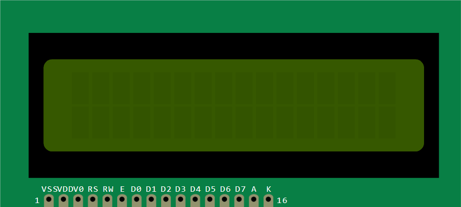
Pin Configuration and Descriptions
The 16x2 LCD module typically has 16 pins. Below is the pinout and description:
| Pin No. | Name | Description |
|---|---|---|
| 1 | VSS | Ground (0V) |
| 2 | VDD | Power supply (4.7V to 5.3V) |
| 3 | VO | Contrast adjustment (connect to a potentiometer for contrast control) |
| 4 | RS | Register Select (0: Command mode, 1: Data mode) |
| 5 | RW | Read/Write (0: Write to LCD, 1: Read from LCD) |
| 6 | E | Enable signal (triggers data read/write) |
| 7 | D0 | Data bit 0 (used in 8-bit mode only) |
| 8 | D1 | Data bit 1 (used in 8-bit mode only) |
| 9 | D2 | Data bit 2 (used in 8-bit mode only) |
| 10 | D3 | Data bit 3 (used in 8-bit mode only) |
| 11 | D4 | Data bit 4 (used in both 4-bit and 8-bit modes) |
| 12 | D5 | Data bit 5 (used in both 4-bit and 8-bit modes) |
| 13 | D6 | Data bit 6 (used in both 4-bit and 8-bit modes) |
| 14 | D7 | Data bit 7 (used in both 4-bit and 8-bit modes) |
| 15 | A (LED+) | Backlight anode (connect to +5V through a resistor if backlight is used) |
| 16 | K (LED-) | Backlight cathode (connect to ground if backlight is used) |
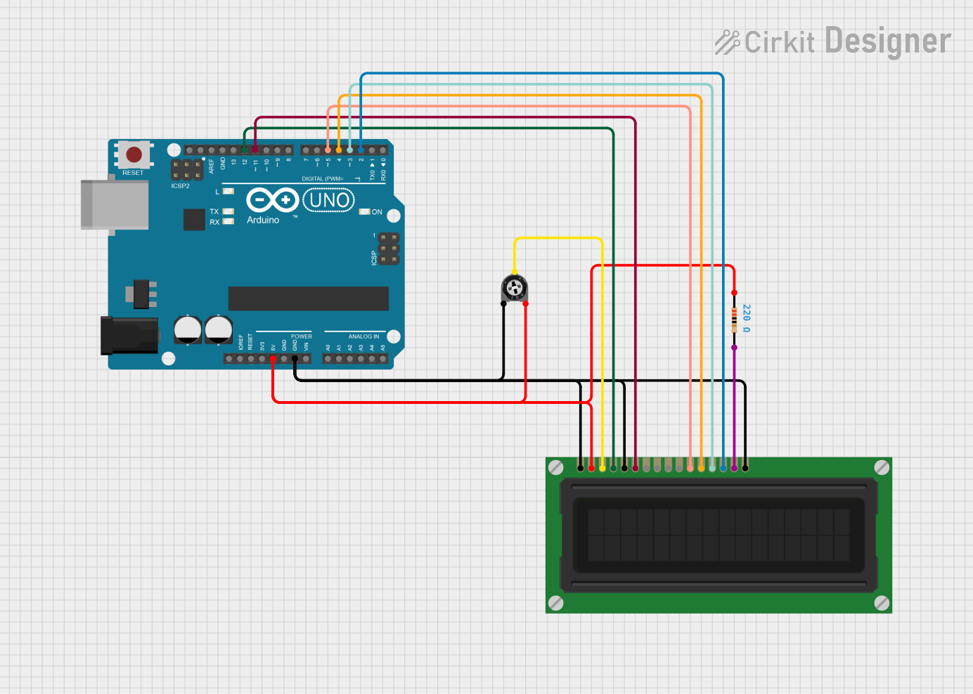
Usage Instructions
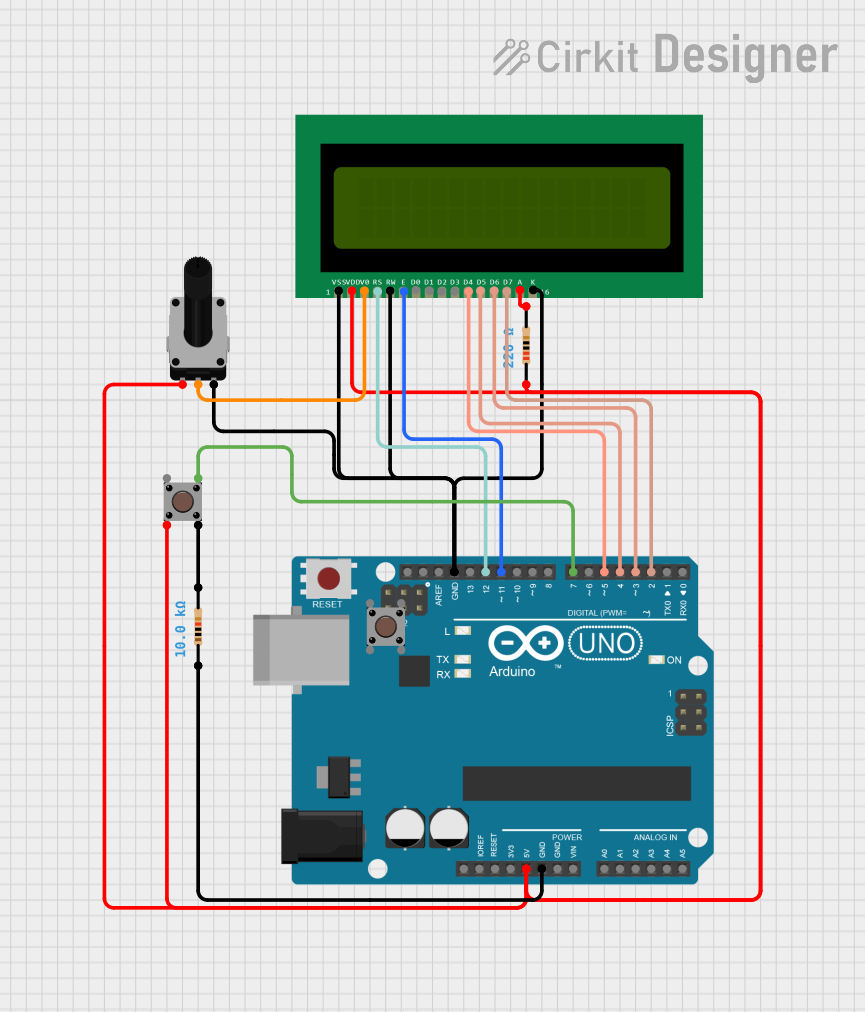
How to Use the 16x2 LCD in a Circuit
- Power the LCD: Connect the VSS pin to ground and the VDD pin to a 5V power supply.
- Adjust Contrast: Connect the VO pin to the wiper of a 10kΩ potentiometer. Connect the other two terminals of the potentiometer to VDD and ground.
- Connect Control Pins:
- RS: Connect to a digital pin on the microcontroller.
- RW: Connect to ground (for write-only mode).
- E: Connect to a digital pin on the microcontroller.
- Connect Data Pins:
- For 4-bit mode: Use D4 to D7 and leave D0 to D3 unconnected.
- For 8-bit mode: Use all data pins (D0 to D7).
- Backlight (Optional): Connect pin 15 (A) to 5V through a 220Ω resistor and pin 16 (K) to ground.
Arduino UNO Example Code
Below is an example of how to use a 16x2 LCD with an Arduino UNO in 4-bit mode:
#include <LiquidCrystal.h>

// Initialize the library with the pins connected to the LCD
// RS, E, D4, D5, D6, D7
LiquidCrystal lcd(7, 8, 9, 10, 11, 12);

void setup() {
  // Set up the LCD's number of columns and rows
  lcd.begin(16, 2);

  // Print a message to the LCD
  lcd.print("Hello, World!");
}

void loop() {
  // Move the cursor to the second line
  lcd.setCursor(0, 1);

  // Print a dynamic message
  lcd.print("Count: ");
  lcd.print(millis() / 1000); // Display elapsed time in seconds
}
Important Considerations and Best Practices
- Always use a current-limiting resistor (220Ω to 1kΩ) for the backlight to prevent damage.
- Use a 10kΩ potentiometer to adjust the contrast for optimal visibility.
- Avoid leaving unused data pins floating; tie them to ground if not used.
- For longer cables, consider adding decoupling capacitors near the LCD power pins to reduce noise.
Troubleshooting and FAQs
Common Issues and Solutions
No Display on the LCD:
- Check the power connections (VSS and VDD).
- Adjust the contrast using the potentiometer connected to VO.
- Ensure the backlight is connected properly (if used).
Garbled or Incorrect Characters:
- Verify the data connections (D4 to D7 for 4-bit mode or D0 to D7 for 8-bit mode).
- Ensure the RS, RW, and E pins are connected correctly.
- Check the code for proper initialization of the LCD.
Backlight Not Working:
- Ensure the backlight pins (A and K) are connected correctly.
- Use a suitable resistor to limit the current to the backlight.
LCD Not Responding to Commands:
- Verify the Enable (E) pin is being toggled correctly in the code.
- Ensure the RW pin is grounded for write-only mode.
FAQs
Q: Can I use the 16x2 LCD with a 3.3V microcontroller?
A: Yes, but you will need a level shifter or resistor voltage dividers for the data and control pins. Additionally, the backlight may not work optimally at 3.3V.
Q: How do I create custom characters on the LCD?
A: The HD44780 controller allows you to define up to 8 custom characters using the lcd.createChar() function in the Arduino library.
Q: Can I use the LCD without a potentiometer for contrast adjustment?
A: Yes, you can connect the VO pin to ground for maximum contrast, but using a potentiometer provides better control.
Q: What is the difference between 4-bit and 8-bit modes?
A: In 4-bit mode, only 4 data pins (D4 to D7) are used, reducing the number of required connections. In 8-bit mode, all 8 data pins (D0 to D7) are used, allowing faster data transfer.