How to Use NDR SWITCH: Examples, Pinouts, and Specs
Introduction
The Non-Destructive Read (NDR) switch is a specialized electronic switch designed to allow signals to pass through without altering or degrading the original signal. This makes it an ideal choice for applications where signal integrity is critical. NDR switches are commonly used in data communication systems, signal routing, and testing environments where precise signal replication is required.
Explore Projects Built with NDR SWITCH
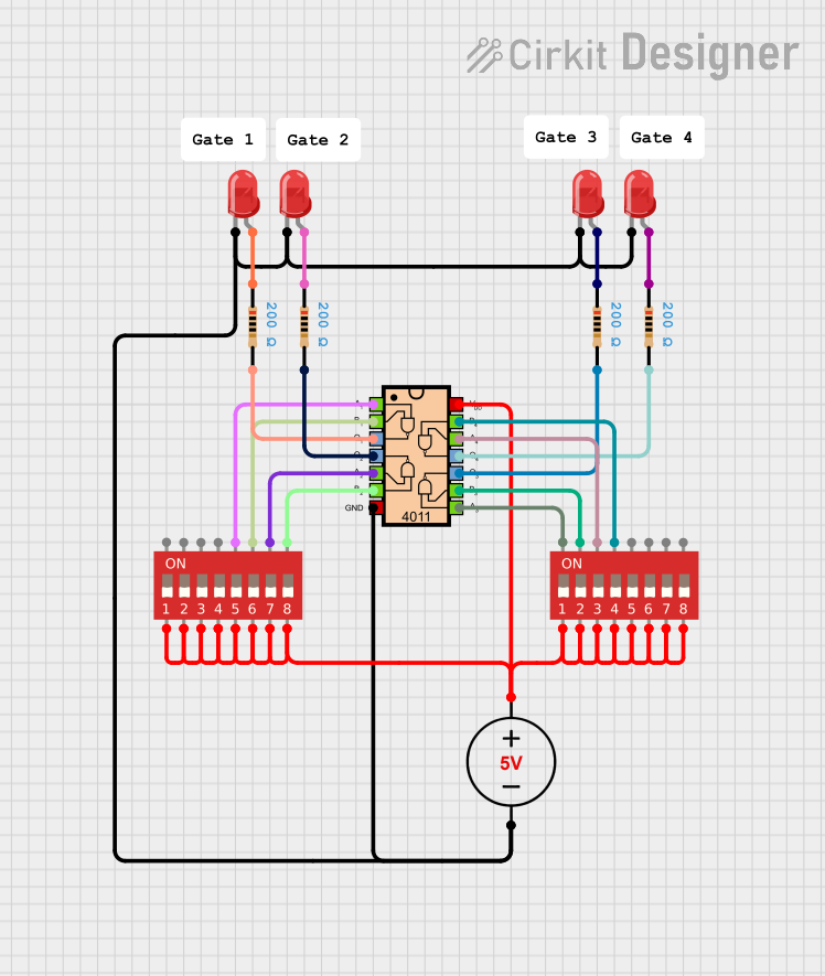

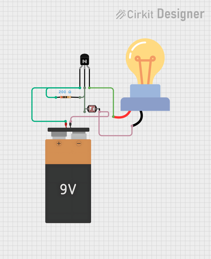

Explore Projects Built with NDR SWITCH
Common Applications and Use Cases
- Data Communication Systems: Ensures signal integrity during transmission.
- Signal Routing: Used in multiplexers and demultiplexers for high-fidelity signal switching.
- Testing and Measurement: Allows non-invasive signal monitoring in test setups.
- Audio and Video Systems: Maintains high-quality signal transmission in AV equipment.
Technical Specifications
Key Technical Details
- Operating Voltage: 3.3V to 5V DC
- Current Rating: Up to 50mA per channel
- Switching Speed: <10ns (nanoseconds)
- Signal Bandwidth: Up to 1GHz
- On-Resistance (RON): Typically 5Ω
- Off-Leakage Current: <1nA
- Temperature Range: -40°C to +85°C
- Control Logic Level: Compatible with TTL and CMOS logic
Pin Configuration and Descriptions
The NDR switch typically comes in an 8-pin or 16-pin package. Below is an example of an 8-pin configuration:
| Pin Number | Pin Name | Description |
|---|---|---|
| 1 | IN1 | Control input for Channel 1 |
| 2 | OUT1 | Signal output for Channel 1 |
| 3 | GND | Ground connection |
| 4 | VCC | Power supply (3.3V to 5V) |
| 5 | OUT2 | Signal output for Channel 2 |
| 6 | IN2 | Control input for Channel 2 |
| 7 | ENABLE | Enables or disables the switch (active high) |
| 8 | NC | No connection (reserved for future use) |
For a 16-pin package, additional channels (e.g., IN3, OUT3, IN4, OUT4) are included.
Usage Instructions
How to Use the NDR Switch in a Circuit
- Power Supply: Connect the VCC pin to a 3.3V or 5V DC power source and the GND pin to the ground.
- Control Inputs: Apply a logic HIGH or LOW signal to the control input pins (e.g., IN1, IN2) to toggle the corresponding channels.
- Signal Connections: Connect the input signal to the OUT pins. The switch will pass the signal through without altering it.
- Enable Pin: Ensure the ENABLE pin is set to HIGH to activate the switch. If set to LOW, the switch will be disabled.
Important Considerations and Best Practices
- Signal Integrity: Use short and low-impedance connections to minimize signal degradation.
- Power Supply Decoupling: Add a 0.1µF ceramic capacitor close to the VCC pin to filter noise.
- Logic Compatibility: Ensure the control signals are within the specified logic level range.
- Thermal Management: Operate the switch within the recommended temperature range to avoid overheating.
Example: Using the NDR Switch with an Arduino UNO
Below is an example of how to control an NDR switch using an Arduino UNO:
// Example: Controlling an NDR Switch with Arduino UNO

// Define control pins for the NDR switch
const int controlPin1 = 2; // Control input for Channel 1
const int controlPin2 = 3; // Control input for Channel 2
const int enablePin = 4;   // Enable pin for the NDR switch

void setup() {
  // Set the control and enable pins as outputs
  pinMode(controlPin1, OUTPUT);
  pinMode(controlPin2, OUTPUT);
  pinMode(enablePin, OUTPUT);

  // Enable the NDR switch
  digitalWrite(enablePin, HIGH);
}

void loop() {
  // Toggle Channel 1 ON and OFF
  digitalWrite(controlPin1, HIGH); // Turn ON Channel 1
  delay(1000);                     // Wait for 1 second
  digitalWrite(controlPin1, LOW);  // Turn OFF Channel 1
  delay(1000);                     // Wait for 1 second

  // Toggle Channel 2 ON and OFF
  digitalWrite(controlPin2, HIGH); // Turn ON Channel 2
  delay(1000);                     // Wait for 1 second
  digitalWrite(controlPin2, LOW);  // Turn OFF Channel 2
  delay(1000);                     // Wait for 1 second
}
Troubleshooting and FAQs
Common Issues and Solutions
No Signal Output:
- Ensure the ENABLE pin is set to HIGH.
- Verify that the control input pins (e.g., IN1, IN2) are receiving the correct logic levels.
- Check the power supply connections (VCC and GND).
Signal Degradation:
- Use high-quality cables and minimize the length of signal traces.
- Add decoupling capacitors near the power supply pins to reduce noise.
Switch Not Responding to Control Signals:
- Confirm that the control signals are within the specified voltage range.
- Check for loose or incorrect wiring.
FAQs
Q1: Can the NDR switch handle analog signals?
Yes, the NDR switch can handle both analog and digital signals, provided the signal voltage is within the specified range.
Q2: What happens if the ENABLE pin is left floating?
Leaving the ENABLE pin floating may cause unpredictable behavior. It is recommended to connect it to a defined logic level (HIGH or LOW).
Q3: Can the NDR switch operate at 1.8V logic levels?
No, the NDR switch is designed for 3.3V to 5V logic levels. Using 1.8V logic may result in unreliable operation.
Q4: Is the NDR switch bidirectional?
Yes, the NDR switch is bidirectional, meaning signals can pass in either direction through the switch.