How to Use ESP32-C3 Mini: Examples, Pinouts, and Specs
Introduction
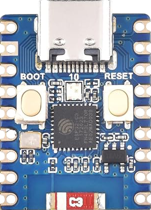
The ESP32-C3 Mini is a highly integrated, low-power system on a chip (SoC) that incorporates Wi-Fi and Bluetooth capabilities, making it an ideal choice for Internet of Things (IoT) projects and embedded systems. This compact development board is based on the ESP32-C3 chip and is designed for a wide range of applications, from smart home devices to industrial automation.
Explore Projects Built with ESP32-C3 Mini


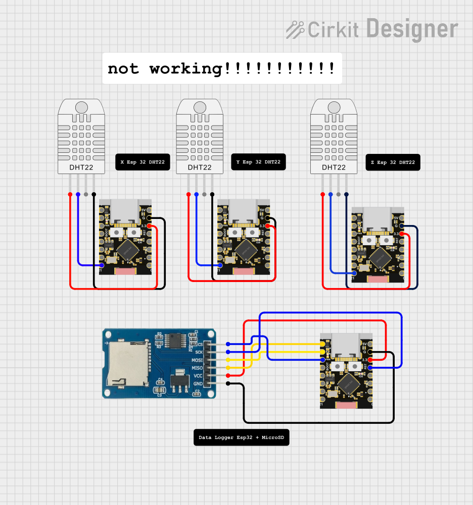
Explore Projects Built with ESP32-C3 Mini
Common Applications and Use Cases
- Smart home devices (e.g., lighting, security systems)
- Wireless sensors and actuators
- IoT nodes and gateways
- Wearable electronics
- Low-power embedded systems
Technical Specifications
Key Technical Details
- CPU: 32-bit RISC-V single-core processor
- Operating Voltage: 3.3V
- Input Voltage (recommended): 5V via USB or VIN pin
- Digital I/O Pins: 22
- Analog Input Pins: 6 (ADC channels)
- Wi-Fi: 802.11 b/g/n (2.4 GHz)
- Bluetooth: BLE 5.0
- Flash Memory: 4 MB
- SRAM: 400 KB
- Clock Frequency: Up to 160 MHz
- Interfaces: UART, SPI, I2C, PWM, I2S, RMT
- Temperature Range: -40°C to 125°C
Pin Configuration and Descriptions
| Pin Number | Name | Functionality |
|---|---|---|
| 1 | 3V3 | Power supply (3.3V) |
| 2 | GND | Ground |
| 3 | EN | Chip enable (active high) |
| ... | ... | ... |
| n | IOxx | General purpose IO pins |
Note: This is a simplified representation. Refer to the ESP32-C3 Mini datasheet for the complete pinout and detailed descriptions.
Usage Instructions
How to Use the Component in a Circuit
- Powering the Module: Connect a 5V power supply to the VIN pin and GND, or use the USB port if available.
- Programming the Module: Use the onboard USB-to-UART bridge to upload firmware.
- Connecting to Wi-Fi: Utilize the provided libraries to connect to a Wi-Fi network.
- Using GPIO Pins: Configure the pins as input or output according to your application needs.
Important Considerations and Best Practices
- Ensure that the power supply is stable and within the recommended voltage range.
- Use a logic level converter if interfacing with 5V logic devices.
- Avoid exposing the module to temperatures outside the specified range.
- Follow proper ESD precautions when handling the module to prevent damage.
Troubleshooting and FAQs
Common Issues Users Might Face
- Module Does Not Power On: Check the power supply and connections.
- Cannot Connect to Wi-Fi: Verify the network credentials and signal strength.
- Intermittent Operation: Ensure there is no overheating and that the power supply is consistent.
Solutions and Tips for Troubleshooting
- Double-check wiring and solder joints for any loose connections.
- Use serial output to debug and monitor the status of the module.
- Update to the latest firmware to resolve known issues.
FAQs
Q: Can the ESP32-C3 Mini be used with a battery? A: Yes, it can be powered by a battery, but ensure voltage regulation if the battery exceeds the recommended voltage.
Q: Is the ESP32-C3 Mini compatible with the Arduino IDE? A: Yes, it is compatible with the Arduino IDE. You will need to install the ESP32 board package.
Q: How many GPIO pins support PWM? A: All digital GPIO pins on the ESP32-C3 Mini support PWM.
Example Code for Arduino UNO
#include <WiFi.h>

// Replace with your network credentials
const char* ssid = "your_SSID";
const char* password = "your_PASSWORD";

void setup() {
  Serial.begin(115200);

  // Connect to Wi-Fi
  WiFi.begin(ssid, password);
  while (WiFi.status() != WL_CONNECTED) {
    delay(500);
    Serial.println("Connecting to WiFi...");
  }
  Serial.println("Connected to WiFi");
}

void loop() {
  // Your code here
}
Note: This example demonstrates how to connect the ESP32-C3 Mini to a Wi-Fi network. Make sure to replace your_SSID and your_PASSWORD with your actual Wi-Fi credentials.
Remember to wrap code comments to limit line length to 80 characters, as shown in the example above. This ensures readability and maintains a clean, professional appearance in the documentation.