How to Use Adafruit Trellis Monochrome Driver PCB for 4x4 Keypad and 3mm LEDs: Examples, Pinouts, and Specs
Introduction
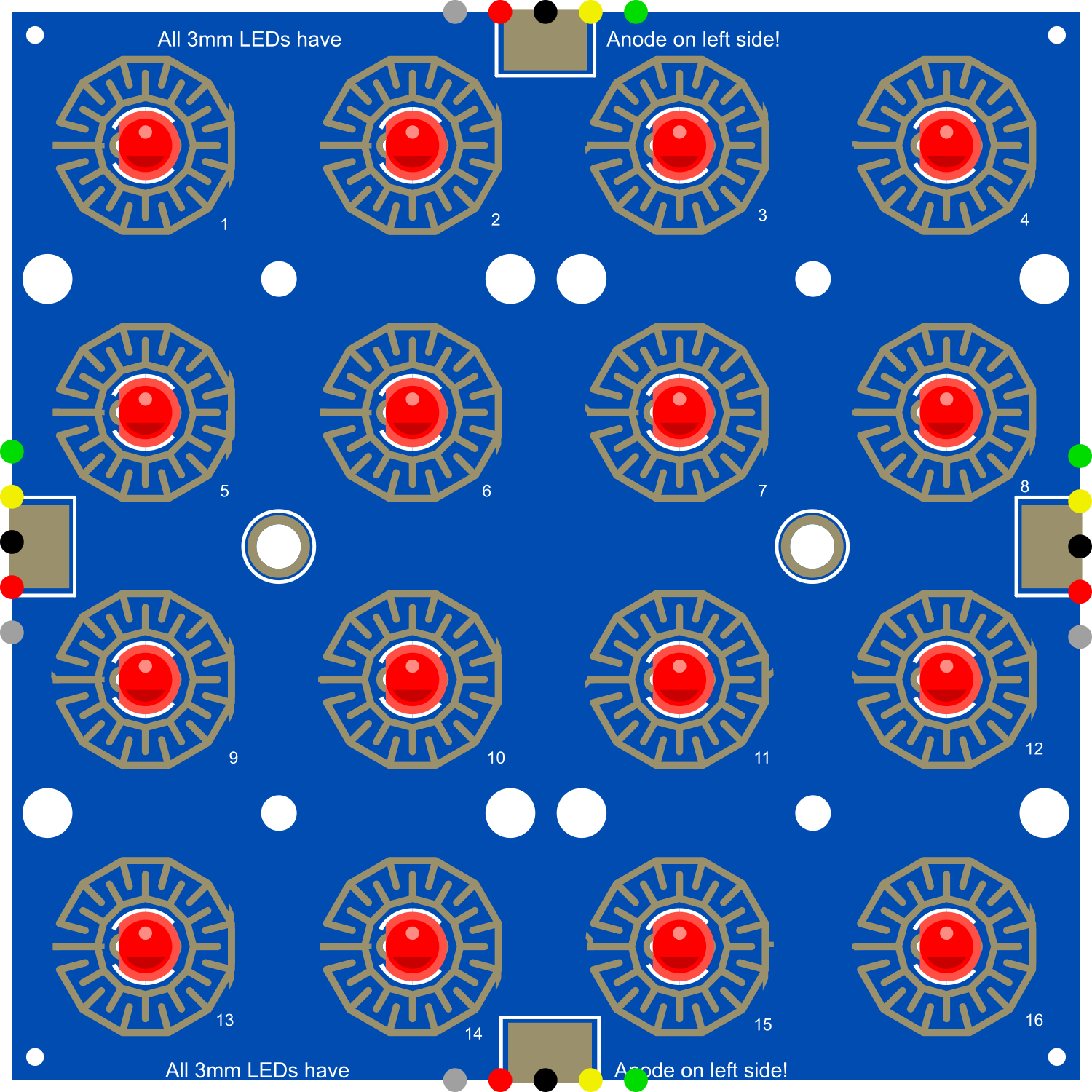
The Adafruit Trellis Monochrome Driver PCB is a unique and versatile component designed for creating interactive LED grids and button interfaces. This driver PCB can control a 4x4 array of buttons and LEDs, making it ideal for DIY projects such as custom keypads, musical instruments, or interactive displays. Its compatibility with microcontrollers, like the Arduino UNO, allows for easy integration into various electronic projects.
Explore Projects Built with Adafruit Trellis Monochrome Driver PCB for 4x4 Keypad and 3mm LEDs
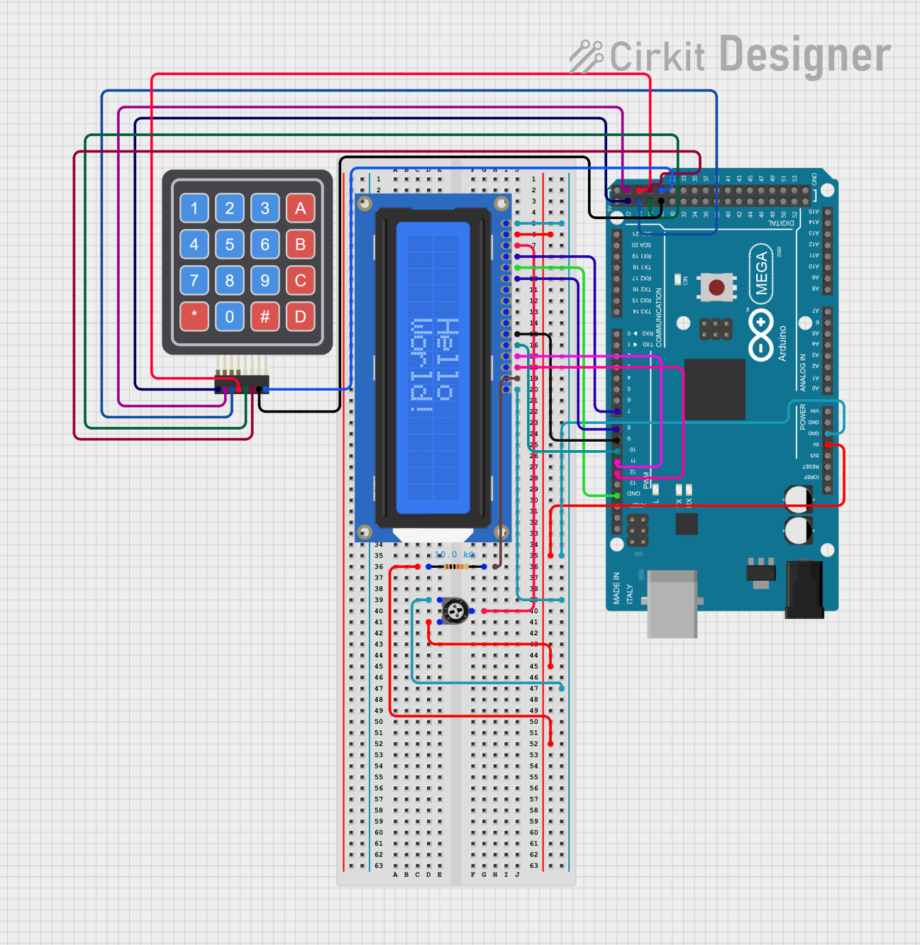


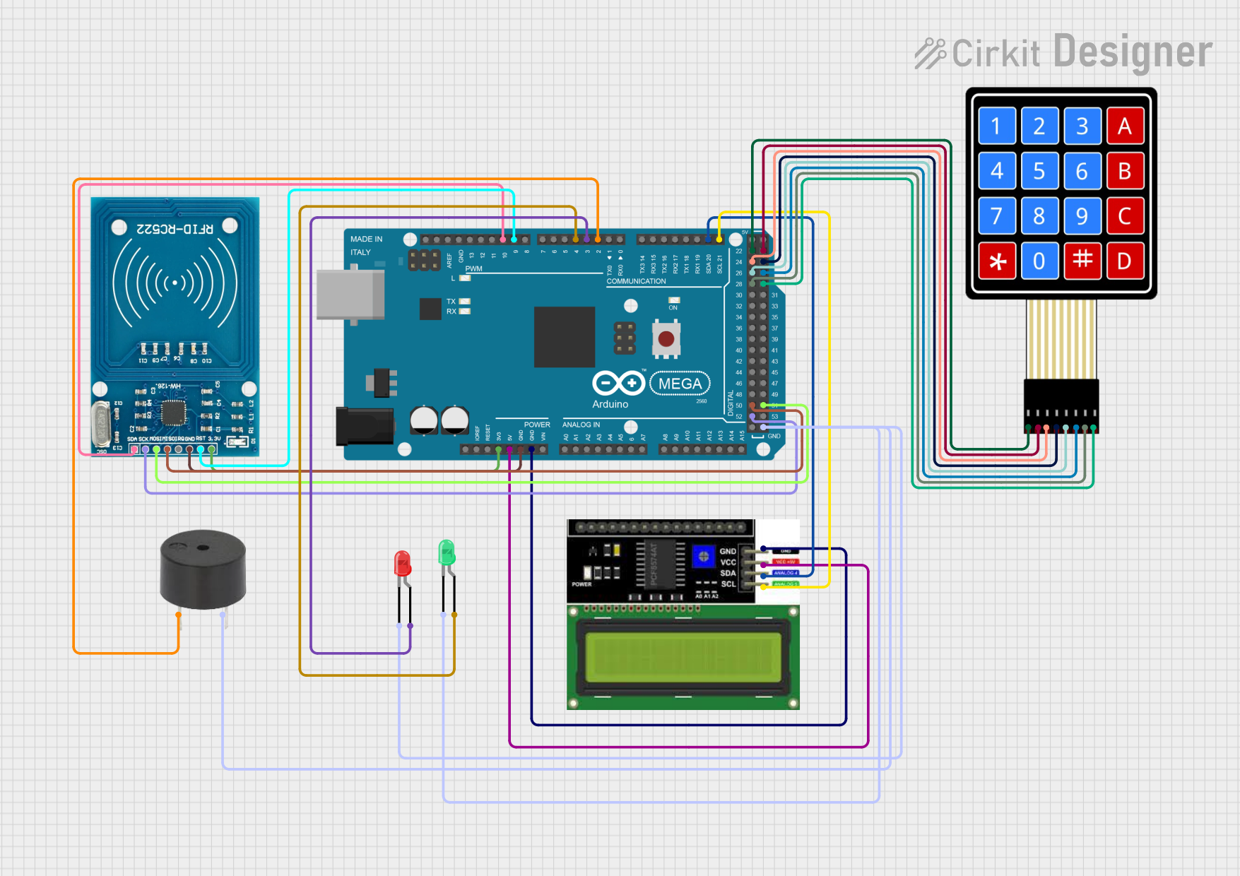
Explore Projects Built with Adafruit Trellis Monochrome Driver PCB for 4x4 Keypad and 3mm LEDs
Common Applications and Use Cases
- Custom keypads for data entry or control panels
- Musical instruments like MIDI controllers
- Interactive LED displays for games or notifications
- Prototyping user interfaces for devices
Technical Specifications
Key Technical Details
- Operating Voltage: 4.5V - 5.5V
- Max Current per LED: 50mA
- Max LEDs powered at once: All 16 with proper power supply
- Communication: I2C interface
- I2C Addresses: Selectable between 0x70 - 0x77 (up to 8 Trellises can be chained)
- Dimensions: 60mm x 60mm x 4.7mm / 2.4" x 2.4" x 0.2"
Pin Configuration and Descriptions
| Pin | Description |
|---|---|
| VCC | Power supply (4.5V - 5.5V) |
| GND | Ground connection |
| SDA | I2C Data Line |
| SCL | I2C Clock Line |
| INT | Interrupt output (active-low) |
| ADDR | Address selection pins (A0, A1, A2) |
| RST | Reset pin (active-low) |
Usage Instructions
How to Use the Component in a Circuit
- Power Connections: Connect the VCC pin to a 5V supply, and the GND pin to the ground on your microcontroller.
- I2C Connections: Connect the SDA and SCL pins to your microcontroller's I2C data and clock lines.
- Address Selection: If using multiple Trellis boards, set unique I2C addresses using the ADDR pins by connecting them to GND or VCC.
- Interrupts (Optional): Connect the INT pin to an interrupt-capable pin on your microcontroller if you wish to use the interrupt feature.
Important Considerations and Best Practices
- Ensure that the power supply can handle the current draw if all LEDs are lit.
- Use pull-up resistors on the I2C lines if your microcontroller does not have built-in pull-ups.
- When chaining multiple Trellis boards, ensure that the total current does not exceed the power supply's capabilities.
- Avoid placing the Trellis board in a high-static environment as it can damage the electronics.
Example Code for Arduino UNO
#include <Wire.h>
#include "Adafruit_Trellis.h"

Adafruit_Trellis matrix0;

void setup() {
  Wire.begin();
  matrix0.begin(0x70);  // Initialize the first Trellis board at I2C address 0x70
  // If chaining boards, initialize additional boards here
}

void loop() {
  // Set LED state
  matrix0.setLED(0);    // Turn on LED at position 0
  matrix0.clrLED(1);    // Turn off LED at position 1
  matrix0.writeDisplay(); // Write the changes to the board

  // Read button state
  if (matrix0.readSwitches()) {
    if (matrix0.justPressed(0)) {
      // Do something when button 0 is pressed
    }
    // Add additional button handling here
  }
  delay(100); // Debounce delay
}
Troubleshooting and FAQs
Common Issues Users Might Face
- LEDs not lighting up: Check the power supply and I2C connections. Ensure that the correct I2C address is being used.
- Unresponsive buttons: Verify that the interrupt pin (if used) is correctly connected and configured.
- Multiple Trellis boards not working together: Ensure that each board has a unique I2C address and that the connections are secure.
Solutions and Tips for Troubleshooting
- Double-check wiring, especially the I2C lines and power connections.
- Use a multimeter to verify that the correct voltage is present at the VCC pin.
- Check for solder bridges or cold solder joints that might be causing shorts or open circuits.
- Consult the Adafruit Trellis library documentation for additional functions and examples.
FAQs
Q: Can I use the Trellis with a 3.3V microcontroller? A: Yes, but ensure that the logic levels are compatible, and you may need level shifters for the I2C lines.
Q: How many Trellis boards can I chain together? A: You can chain up to 8 Trellis boards together, each with a unique I2C address.
Q: Can I control the brightness of the LEDs? A: The LEDs are either on or off; there is no built-in brightness control. However, you can simulate brightness control using PWM techniques with your microcontroller.
For further assistance, visit the Adafruit support forums or the product's FAQ page on the Adafruit website.