
How to Use Adafruit bq25185 USB - DC - Solar Lithium Ion Polymer Charger: Examples, Pinouts, and Specs
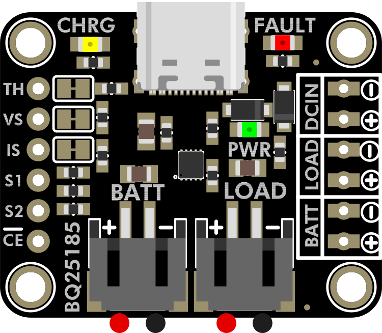
 Design with Adafruit bq25185 USB - DC - Solar Lithium Ion Polymer Charger in Cirkit Designer
Introduction
The Adafruit bq25185 USB - DC - Solar Lithium Ion Polymer Charger (Part ID: 6091) is a versatile and efficient charging module designed for Lithium Ion and Lithium Polymer batteries. It supports multiple power input sources, including USB, DC input, and solar panels, making it ideal for portable and renewable energy projects. The charger integrates a battery management system (BMS) to ensure safe and reliable operation, with features such as overcharge protection, thermal regulation, and programmable charge rates.
Explore Projects Built with Adafruit bq25185 USB - DC - Solar Lithium Ion Polymer Charger
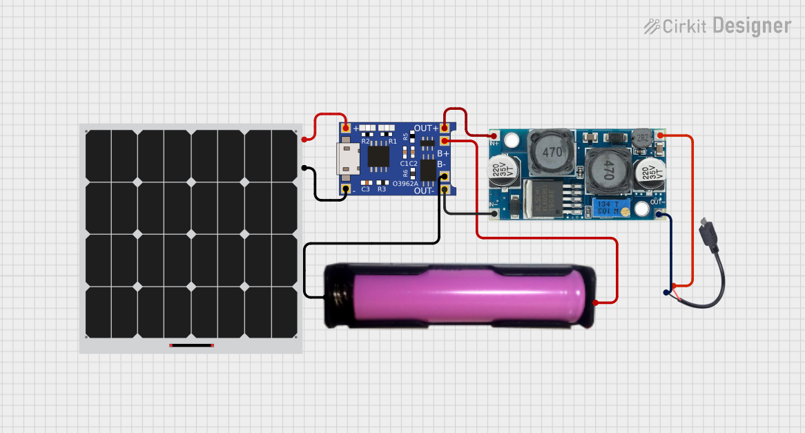 Open Project in Cirkit Designer
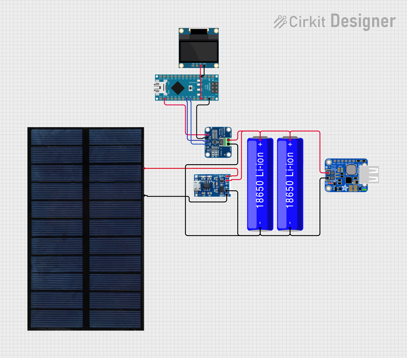 Open Project in Cirkit Designer
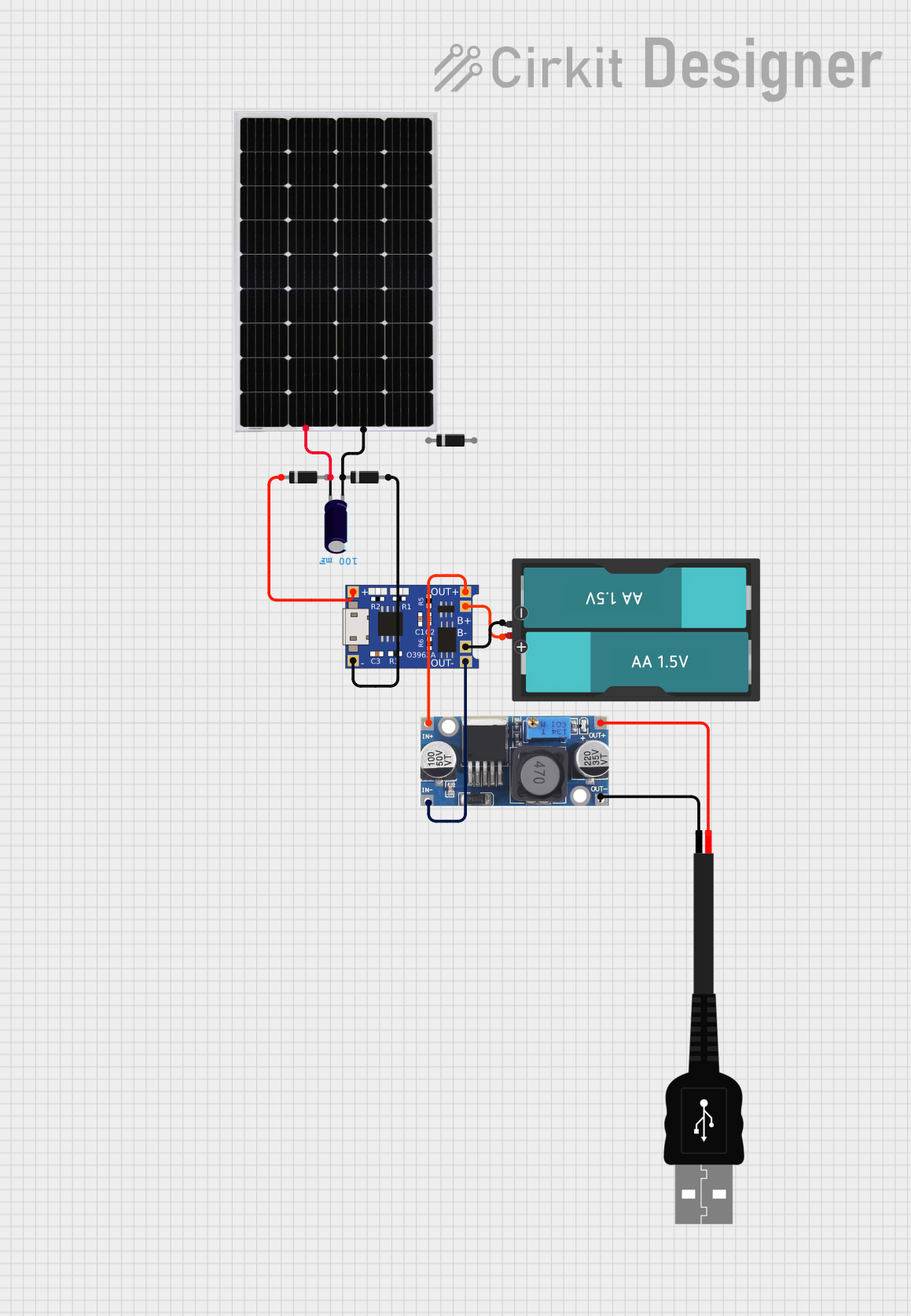 Open Project in Cirkit Designer
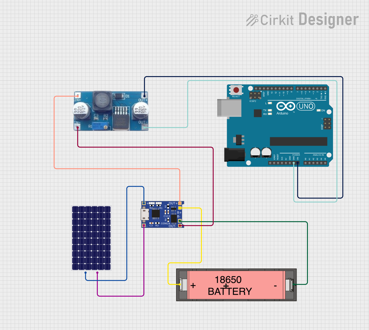 Open Project in Cirkit Designer
Explore Projects Built with Adafruit bq25185 USB - DC - Solar Lithium Ion Polymer Charger
Open Project in Cirkit DesignerOpen Project in Cirkit DesignerOpen Project in Cirkit DesignerOpen Project in Cirkit DesignerCommon Applications and Use Cases
- Portable electronics powered by Lithium Ion/Polymer batteries
- Solar-powered IoT devices and wearables
- Battery backup systems
- DIY renewable energy projects
- Prototyping and development of battery-powered devices
Technical Specifications
The Adafruit bq25185 charger is built around the Texas Instruments bq25185 PMIC (Power Management Integrated Circuit). Below are the key technical details:
Key Technical Details
- Input Voltage Range: 3.5V to 17V (USB, DC, or solar input)
- Battery Voltage Range: 3.6V to 4.4V (programmable)
- Maximum Charge Current: Up to 1.2A (programmable)
- Input Current Limit: 100mA to 1.5A (programmable)
- Battery Protection: Overcharge, over-discharge, and short-circuit protection
- Operating Temperature: -40°C to +85°C
- Power Path Management: Supports simultaneous charging and powering of the load
- Interface: I2C for configuration and monitoring
- Dimensions: 25mm x 25mm (1" x 1")
Pin Configuration and Descriptions
The Adafruit bq25185 charger has the following pinout:
| Pin Name | Type | Description |
|---|---|---|
| VIN | Power Input | Main power input (3.5V to 17V) for USB, DC, or solar panel. |
| GND | Power Ground | Ground connection for the module. |
| BAT | Power Output | Battery connection for charging and discharging. |
| SYS | Power Output | System output for powering the load (regulated by the power path management). |
| SDA | I2C Data | I2C data line for communication with a microcontroller. |
| SCL | I2C Clock | I2C clock line for communication with a microcontroller. |
| EN | Input | Enable pin to turn the charger on/off. Active high. |
| STAT | Output | Status indicator pin (e.g., charging, fault). |
| PG | Output | Power Good indicator pin for input power status. |
| TS | Input | Thermistor input for battery temperature monitoring. |
Usage Instructions
How to Use the Component in a Circuit
- Power Input: Connect a power source (USB, DC, or solar panel) to the
VINpin. Ensure the input voltage is within the range of 3.5V to 17V. - Battery Connection: Attach a Lithium Ion or Lithium Polymer battery to the
BATpin. Ensure the battery is compatible with the charger’s voltage range (3.6V to 4.4V). - Load Connection: Connect your device or load to the
SYSpin. The charger will manage power distribution between the battery and the load. - I2C Communication: If needed, connect the
SDAandSCLpins to a microcontroller (e.g., Arduino) for configuration and monitoring. - Thermistor: Optionally, connect a 10kΩ NTC thermistor to the
TSpin for battery temperature monitoring.
Important Considerations and Best Practices
- Input Source Selection: When using a solar panel, ensure it provides sufficient voltage and current under typical lighting conditions.
- Battery Safety: Use only Lithium Ion or Lithium Polymer batteries with built-in protection circuits to prevent over-discharge or short circuits.
- Heat Dissipation: Ensure adequate ventilation or heat sinking if the charger operates at high currents for extended periods.
- I2C Pull-Up Resistors: Add external pull-up resistors (typically 4.7kΩ) to the
SDAandSCLlines if not already present in your circuit.
Example Arduino Code
Below is an example of how to configure and monitor the Adafruit bq25185 charger using an Arduino UNO via I2C:
#include <Wire.h>

// I2C address of the bq25185 charger
#define BQ25185_I2C_ADDRESS 0x6B

void setup() {
  Wire.begin(); // Initialize I2C communication
  Serial.begin(9600); // Initialize serial communication for debugging

  // Configure the charger (example: set charge current to 500mA)
  Wire.beginTransmission(BQ25185_I2C_ADDRESS);
  Wire.write(0x03); // Register address for charge current control
  Wire.write(0x50); // Set charge current to 500mA (example value)
  Wire.endTransmission();

  Serial.println("Charger configured.");
}

void loop() {
  // Read charger status
  Wire.beginTransmission(BQ25185_I2C_ADDRESS);
  Wire.write(0x0A); // Register address for status
  Wire.endTransmission();
  Wire.requestFrom(BQ25185_I2C_ADDRESS, 1);

  if (Wire.available()) {
    uint8_t status = Wire.read();
    Serial.print("Charger Status: 0x");
    Serial.println(status, HEX);
  }

  delay(1000); // Wait 1 second before the next status check
}
Troubleshooting and FAQs
Common Issues and Solutions
Charger Not Powering On
- Cause: Insufficient input voltage or incorrect wiring.
- Solution: Verify the input voltage is within the 3.5V to 17V range and check all connections.
Battery Not Charging
- Cause: Faulty battery or incorrect configuration.
- Solution: Ensure the battery is properly connected and compatible. Check the charge current and voltage settings via I2C.
Overheating
- Cause: High charge current or poor ventilation.
- Solution: Reduce the charge current or improve heat dissipation.
I2C Communication Fails
- Cause: Missing pull-up resistors or incorrect wiring.
- Solution: Add 4.7kΩ pull-up resistors to the
SDAandSCLlines and verify connections.
FAQs
Can I use this charger with a 6V solar panel? Yes, as long as the panel provides sufficient current and the voltage stays within the 3.5V to 17V range.
What happens if the input power is disconnected? The charger will seamlessly switch to battery power to maintain the load.
Is the charger compatible with LiFePO4 batteries? No, this charger is designed for Lithium Ion and Lithium Polymer batteries only.
Can I adjust the charge voltage? Yes, the charge voltage is programmable via I2C within the range of 3.6V to 4.4V.