Cirkit Designer Logo
Cirkit Designer
Your all-in-one circuit design IDE
Home / 
Component Documentation

How to Use USB Charger for bike: Examples, Pinouts, and Specs

Image of USB Charger for bike
Cirkit Designer LogoDesign with USB Charger for bike in Cirkit Designer

Introduction

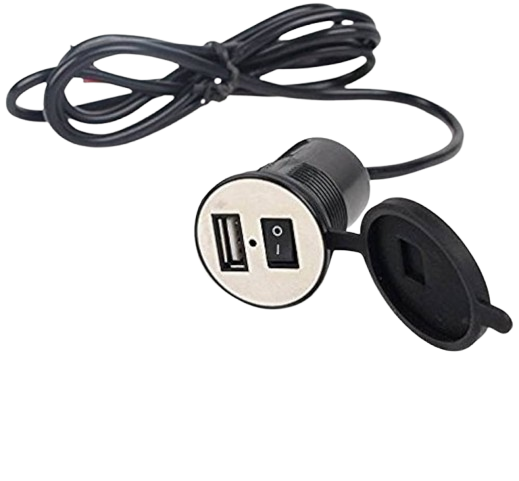
The USB Charger for Bike is a versatile device designed to convert the electrical energy generated by a bicycle's dynamo or battery into a USB-compatible output. This allows cyclists to charge electronic devices such as smartphones, GPS units, and other USB-powered gadgets while riding. This component is particularly useful for long-distance cyclists, bike commuters, and outdoor enthusiasts who need to keep their devices powered on the go.

Explore Projects Built with USB Charger for bike

Use Cirkit Designer to design, explore, and prototype these projects online. Some projects support real-time simulation. Click "Open Project" to start designing instantly!
Battery-Powered USB Charger with LED Indicator and DC Motor
Image of Copy of Hand Crank mobile charger : A project utilizing USB Charger for bike in a practical application
This circuit converts AC power to DC using a bridge rectifier and regulates the voltage to 5V with a 7805 voltage regulator. It powers a USB port and indicates power status with an LED, while also providing a charging interface through a multi-charging cable.
Cirkit Designer LogoOpen Project in Cirkit Designer
Battery-Powered DC Motor Control with USB Charging and LED Indicator
Image of lumantas: A project utilizing USB Charger for bike in a practical application
This circuit is designed to charge a Li-ion battery and power a DC motor and a 12V LED. The TP4056 module manages the battery charging process, while the PowerBoost 1000 and MT3608 boost converters step up the voltage to drive the motor and LED, respectively. Two rocker switches control the power flow to the LED and the charging circuit.
Cirkit Designer LogoOpen Project in Cirkit Designer
Battery-Powered Lora G2 Node Station with 18650 Li-ion Batteries and Boost Converter
Image of Custom-Lora-G2-Node: A project utilizing USB Charger for bike in a practical application
This circuit is a portable power supply system that uses multiple 18650 Li-ion batteries to provide a stable 5V output through a boost converter. It includes a fast charging module with a USB-C input for recharging the batteries and a battery indicator for monitoring the battery status. The system powers a Lora G2 Node Station, making it suitable for wireless communication applications.
Cirkit Designer LogoOpen Project in Cirkit Designer
Solar-Powered USB Charger with Voltage Regulation and LED Indicator
Image of Solar mobile charger : A project utilizing USB Charger for bike in a practical application
This circuit appears to be a solar-powered USB charging circuit with voltage regulation and an LED indicator. A solar cell charges a USB device through a 7805 voltage regulator, ensuring a stable 5V output. An electrolytic capacitor smooths the input voltage, while a resistor limits current to the LED, which likely serves as a power-on indicator.
Cirkit Designer LogoOpen Project in Cirkit Designer

Explore Projects Built with USB Charger for bike

Use Cirkit Designer to design, explore, and prototype these projects online. Some projects support real-time simulation. Click "Open Project" to start designing instantly!
Image of Copy of Hand Crank mobile charger : A project utilizing USB Charger for bike in a practical application
Battery-Powered USB Charger with LED Indicator and DC Motor
This circuit converts AC power to DC using a bridge rectifier and regulates the voltage to 5V with a 7805 voltage regulator. It powers a USB port and indicates power status with an LED, while also providing a charging interface through a multi-charging cable.
Cirkit Designer LogoOpen Project in Cirkit Designer
Image of lumantas: A project utilizing USB Charger for bike in a practical application
Battery-Powered DC Motor Control with USB Charging and LED Indicator
This circuit is designed to charge a Li-ion battery and power a DC motor and a 12V LED. The TP4056 module manages the battery charging process, while the PowerBoost 1000 and MT3608 boost converters step up the voltage to drive the motor and LED, respectively. Two rocker switches control the power flow to the LED and the charging circuit.
Cirkit Designer LogoOpen Project in Cirkit Designer
Image of Custom-Lora-G2-Node: A project utilizing USB Charger for bike in a practical application
Battery-Powered Lora G2 Node Station with 18650 Li-ion Batteries and Boost Converter
This circuit is a portable power supply system that uses multiple 18650 Li-ion batteries to provide a stable 5V output through a boost converter. It includes a fast charging module with a USB-C input for recharging the batteries and a battery indicator for monitoring the battery status. The system powers a Lora G2 Node Station, making it suitable for wireless communication applications.
Cirkit Designer LogoOpen Project in Cirkit Designer
Image of Solar mobile charger : A project utilizing USB Charger for bike in a practical application
Solar-Powered USB Charger with Voltage Regulation and LED Indicator
This circuit appears to be a solar-powered USB charging circuit with voltage regulation and an LED indicator. A solar cell charges a USB device through a 7805 voltage regulator, ensuring a stable 5V output. An electrolytic capacitor smooths the input voltage, while a resistor limits current to the LED, which likely serves as a power-on indicator.
Cirkit Designer LogoOpen Project in Cirkit Designer

Technical Specifications

Key Technical Details

Parameter Value
Input Voltage 6V - 12V (AC/DC)
Output Voltage 5V (DC)
Output Current 1A (max)
Power Rating 5W
Efficiency 85%
USB Port Standard USB Type-A
Protection Over-voltage, Over-current
Dimensions 50mm x 30mm x 20mm
Weight 30g

Pin Configuration and Descriptions

Pin No. Pin Name Description
1 V_in Input voltage from dynamo or battery (6V - 12V)
2 GND Ground
3 USB+ USB positive data line (for data transfer)
4 USB- USB negative data line (for data transfer)
5 V_out 5V output to USB port

Usage Instructions

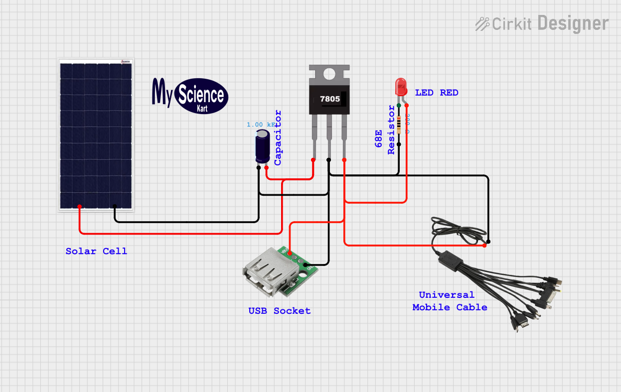
How to Use the Component in a Circuit

  1. Connect the Input Voltage:

    • Connect the V_in pin to the output of your bicycle's dynamo or battery. Ensure the input voltage is within the range of 6V to 12V.
    • Connect the GND pin to the ground of your dynamo or battery.
  2. Connect the USB Device:

    • Plug your USB device into the USB Type-A port of the charger.
  3. Mounting:

    • Securely mount the USB charger on your bicycle frame using zip ties or a mounting bracket to prevent it from moving during the ride.

Important Considerations and Best Practices

  • Voltage Range: Ensure the input voltage is within the specified range (6V - 12V). Exceeding this range can damage the charger.
  • Waterproofing: If you plan to use the charger in wet conditions, ensure it is properly waterproofed or housed in a waterproof enclosure.
  • Heat Dissipation: Avoid placing the charger in a location where it can overheat. Ensure adequate ventilation.
  • Cable Management: Use cable ties to manage and secure cables to prevent them from getting caught in the bike's moving parts.

Troubleshooting and FAQs

Common Issues Users Might Face

  1. No Output Voltage:

    • Solution: Check the input voltage to ensure it is within the specified range. Verify all connections are secure and correct.
  2. Device Not Charging:

    • Solution: Ensure the USB cable and device are functioning properly. Try using a different USB cable or device to isolate the issue.
  3. Overheating:

    • Solution: Ensure the charger is not placed in a confined space without ventilation. Check for any obstructions that may be blocking airflow.

FAQs

Q: Can I use this charger with any USB device? A: Yes, as long as the device requires a 5V input and does not exceed 1A current draw.

Q: Is the charger compatible with both AC and DC input? A: Yes, the charger can accept both AC and DC input within the range of 6V to 12V.

Q: How do I know if the charger is working? A: Most chargers have an LED indicator that lights up when the charger is receiving power and functioning correctly.

Q: Can I use this charger in rainy conditions? A: Yes, but ensure the charger is properly waterproofed or housed in a waterproof enclosure to prevent damage.

Example Code for Arduino UNO

If you want to monitor the charging status using an Arduino UNO, you can use the following code. This example assumes you have connected the charger's output to the Arduino's analog input pin A0.

// Define the analog input pin
const int analogPin = A0;

// Define the threshold voltage (in millivolts)
const int thresholdVoltage = 4500; // 4.5V

void setup() {
  // Initialize serial communication at 9600 baud rate
  Serial.begin(9600);
}

void loop() {
  // Read the analog input value
  int sensorValue = analogRead(analogPin);

  // Convert the analog value to voltage (in millivolts)
  float voltage = sensorValue * (5.0 / 1023.0) * 1000;

  // Print the voltage to the serial monitor
  Serial.print("Voltage: ");
  Serial.print(voltage);
  Serial.println(" mV");

  // Check if the voltage is above the threshold
  if (voltage > thresholdVoltage) {
    Serial.println("Charging...");
  } else {
    Serial.println("Not Charging...");
  }

  // Wait for 1 second before the next reading
  delay(1000);
}

This code reads the voltage from the charger's output and prints it to the serial monitor. It also indicates whether the connected device is charging based on a threshold voltage.

By following this documentation, you should be able to effectively use and troubleshoot the USB Charger for Bike, ensuring your devices stay powered during your rides.