Cirkit Designer Logo
Cirkit Designer
Your all-in-one circuit design IDE
Home / 
Component Documentation

How to Use ESP32: Examples, Pinouts, and Specs

Image of ESP32
Cirkit Designer LogoDesign with ESP32 in Cirkit Designer

Introduction

The ESP32 is a powerful, low-cost microcontroller with integrated Wi-Fi and Bluetooth capabilities, making it an excellent choice for Internet of Things (IoT) applications and embedded systems. Developed by Espressif Systems, the ESP32 is widely used in smart home devices, wearable electronics, industrial automation, and more. Its dual-core processor, extensive GPIO options, and support for various communication protocols make it a versatile and efficient solution for a wide range of projects.

Common applications of the ESP32 include:

  • IoT devices and smart home automation
  • Wireless sensor networks
  • Wearable technology
  • Robotics and industrial control systems
  • Audio streaming and Bluetooth-enabled devices

Explore Projects Built with ESP32

Use Cirkit Designer to design, explore, and prototype these projects online. Some projects support real-time simulation. Click "Open Project" to start designing instantly!
ESP32-Based Sensor Monitoring System with OLED Display and E-Stop
Image of MVP_design: A project utilizing ESP32 in a practical application
This circuit features an ESP32 microcontroller that interfaces with a variety of sensors and output devices. It is powered by a Lipo battery through a buck converter, ensuring a stable voltage supply. The ESP32 collects data from a DHT11 temperature and humidity sensor and a vibration sensor, controls a buzzer, and displays information on an OLED screen. An emergency stop (E Stop) is connected for safety purposes, allowing the system to be quickly deactivated.
Cirkit Designer LogoOpen Project in Cirkit Designer
ESP32-Based NTP Clock with DHT22 Temperature Sensor and WS2812 LED Matrix Display
Image of date time and temperature display : A project utilizing ESP32 in a practical application
This circuit features an ESP32 Devkit V1 microcontroller connected to a DHT22 temperature and humidity sensor and an 8x8 WS2812 RGB LED matrix. The ESP32 reads temperature data from the DHT22 sensor and displays the current date, time, and temperature on the LED matrix, with date and time synchronized via NTP (Network Time Protocol). The ESP32 provides power to both the DHT22 and the LED matrix and communicates with the DHT22 via GPIO 4 and with the LED matrix via GPIO 5.
Cirkit Designer LogoOpen Project in Cirkit Designer
ESP32-Based Environmental Monitoring System with Water Flow Sensing
Image of Water: A project utilizing ESP32 in a practical application
This circuit features an ESP32 Devkit V1 microcontroller connected to a DHT22 temperature and humidity sensor and a water flow sensor. The ESP32 reads environmental data from the DHT22 via a digital input pin (D33) and monitors water flow through the water flow sensor connected to another digital input pin (D23). The ESP32 is powered through its VIN pin, and both sensors are powered by the ESP32's 3V3 output, with common ground connections.
Cirkit Designer LogoOpen Project in Cirkit Designer
ESP32-Based Smart Weather Station with Wi-Fi Connectivity
Image of flowchart 3D: A project utilizing ESP32 in a practical application
This circuit features an ESP32 microcontroller interfacing with various sensors and modules, including a DHT22 temperature and humidity sensor, an ESP32 CAM for image capture, an I2C LCD screen for display, a load cell with an HX711 interface for weight measurement, and a buzzer for audio alerts. The ESP32 handles data acquisition, processing, and communication with these peripherals to create a multi-functional monitoring and alert system.
Cirkit Designer LogoOpen Project in Cirkit Designer

Explore Projects Built with ESP32

Use Cirkit Designer to design, explore, and prototype these projects online. Some projects support real-time simulation. Click "Open Project" to start designing instantly!
Image of MVP_design: A project utilizing ESP32 in a practical application
ESP32-Based Sensor Monitoring System with OLED Display and E-Stop
This circuit features an ESP32 microcontroller that interfaces with a variety of sensors and output devices. It is powered by a Lipo battery through a buck converter, ensuring a stable voltage supply. The ESP32 collects data from a DHT11 temperature and humidity sensor and a vibration sensor, controls a buzzer, and displays information on an OLED screen. An emergency stop (E Stop) is connected for safety purposes, allowing the system to be quickly deactivated.
Cirkit Designer LogoOpen Project in Cirkit Designer
Image of date time and temperature display : A project utilizing ESP32 in a practical application
ESP32-Based NTP Clock with DHT22 Temperature Sensor and WS2812 LED Matrix Display
This circuit features an ESP32 Devkit V1 microcontroller connected to a DHT22 temperature and humidity sensor and an 8x8 WS2812 RGB LED matrix. The ESP32 reads temperature data from the DHT22 sensor and displays the current date, time, and temperature on the LED matrix, with date and time synchronized via NTP (Network Time Protocol). The ESP32 provides power to both the DHT22 and the LED matrix and communicates with the DHT22 via GPIO 4 and with the LED matrix via GPIO 5.
Cirkit Designer LogoOpen Project in Cirkit Designer
Image of Water: A project utilizing ESP32 in a practical application
ESP32-Based Environmental Monitoring System with Water Flow Sensing
This circuit features an ESP32 Devkit V1 microcontroller connected to a DHT22 temperature and humidity sensor and a water flow sensor. The ESP32 reads environmental data from the DHT22 via a digital input pin (D33) and monitors water flow through the water flow sensor connected to another digital input pin (D23). The ESP32 is powered through its VIN pin, and both sensors are powered by the ESP32's 3V3 output, with common ground connections.
Cirkit Designer LogoOpen Project in Cirkit Designer
Image of flowchart 3D: A project utilizing ESP32 in a practical application
ESP32-Based Smart Weather Station with Wi-Fi Connectivity
This circuit features an ESP32 microcontroller interfacing with various sensors and modules, including a DHT22 temperature and humidity sensor, an ESP32 CAM for image capture, an I2C LCD screen for display, a load cell with an HX711 interface for weight measurement, and a buzzer for audio alerts. The ESP32 handles data acquisition, processing, and communication with these peripherals to create a multi-functional monitoring and alert system.
Cirkit Designer LogoOpen Project in Cirkit Designer

Technical Specifications

The ESP32 is packed with features that make it a standout microcontroller for modern applications. Below are its key technical specifications:

General Specifications

  • Processor: Dual-core Xtensa® 32-bit LX6 microprocessor
  • Clock Speed: Up to 240 MHz
  • RAM: 520 KB SRAM
  • Flash Memory: Typically 4 MB (varies by module)
  • Wi-Fi: 802.11 b/g/n (2.4 GHz)
  • Bluetooth: v4.2 BR/EDR and BLE
  • Operating Voltage: 3.3V
  • GPIO Pins: 34 (multipurpose, including ADC, DAC, PWM, I2C, SPI, UART)
  • ADC Channels: 18 (12-bit resolution)
  • DAC Channels: 2 (8-bit resolution)
  • Power Consumption: Ultra-low power consumption with multiple power modes

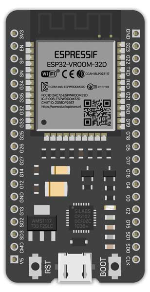
Pin Configuration and Descriptions

The ESP32 has a variety of pins for different functionalities. Below is a table summarizing the key pins and their descriptions:

Pin Name Function Description
GPIO0 Input/Output, Boot Mode Selection Used for general I/O or to select boot mode during startup.
GPIO2 Input/Output, ADC, DAC General-purpose I/O, supports ADC and DAC functionality.
GPIO12 Input/Output, ADC, Touch Sensor General-purpose I/O, supports ADC and capacitive touch sensing.
GPIO13 Input/Output, ADC, Touch Sensor General-purpose I/O, supports ADC and capacitive touch sensing.
GPIO15 Input/Output, ADC, PWM General-purpose I/O, supports ADC and PWM functionality.
EN Enable Active-high pin to enable or reset the chip.
3V3 Power Provides 3.3V power output.
GND Ground Ground connection.
TX0 (GPIO1) UART Transmit UART0 transmit pin for serial communication.
RX0 (GPIO3) UART Receive UART0 receive pin for serial communication.

For a complete pinout, refer to the ESP32 datasheet or module-specific documentation.

Usage Instructions

The ESP32 is highly versatile and can be used in a variety of circuits. Below are the steps to get started with the ESP32:

Setting Up the ESP32 with Arduino IDE

  1. Install the ESP32 Board Package:

    • Open the Arduino IDE.
    • Go to File > Preferences.
    • In the "Additional Board Manager URLs" field, add the following URL:
      https://dl.espressif.com/dl/package_esp32_index.json
      
    • Go to Tools > Board > Boards Manager, search for "ESP32," and install the package.
  2. Connect the ESP32 to Your Computer:

    • Use a USB cable to connect the ESP32 to your computer.
    • Select the correct board and port in the Arduino IDE:
      • Tools > Board > ESP32 Dev Module
      • Tools > Port > [Your ESP32 Port]
  3. Upload a Test Sketch:

    • Use the following example code to test the ESP32:
// Blink example for ESP32
// This code blinks the built-in LED on the ESP32 board.

#define LED_PIN 2  // Built-in LED is usually connected to GPIO2

void setup() {
  pinMode(LED_PIN, OUTPUT);  // Set LED pin as output
}

void loop() {
  digitalWrite(LED_PIN, HIGH);  // Turn the LED on
  delay(1000);                  // Wait for 1 second
  digitalWrite(LED_PIN, LOW);   // Turn the LED off
  delay(1000);                  // Wait for 1 second
}
  1. Upload the Code:
    • Click the upload button in the Arduino IDE.
    • If the upload fails, press and hold the "BOOT" button on the ESP32 while uploading.

Important Considerations

  • Power Supply: Ensure the ESP32 is powered with a stable 3.3V source. Avoid exceeding the voltage limit to prevent damage.
  • Boot Mode: Some ESP32 modules require pressing the "BOOT" button during programming.
  • GPIO Limitations: Certain GPIO pins have specific functions or restrictions (e.g., GPIO0 is used for boot mode selection).

Troubleshooting and FAQs

Common Issues

  1. Upload Fails with Timeout Error:

    • Solution: Press and hold the "BOOT" button on the ESP32 while uploading the code.
  2. ESP32 Not Detected by Computer:

    • Solution: Ensure the USB cable is data-capable (not just for charging). Check the drivers for the USB-to-serial chip (e.g., CP2102 or CH340).
  3. Wi-Fi Connection Issues:

    • Solution: Double-check the SSID and password in your code. Ensure the Wi-Fi network is 2.4 GHz, as the ESP32 does not support 5 GHz networks.
  4. Random Resets or Instability:

    • Solution: Verify the power supply. Use a capacitor to stabilize the power if necessary.

FAQs

  • Q: Can the ESP32 run on 5V?

    • A: No, the ESP32 operates at 3.3V. Applying 5V to its GPIO pins can damage the chip.
  • Q: How do I use the ESP32's Bluetooth functionality?

    • A: The ESP32 supports both Bluetooth Classic and BLE. Use the BluetoothSerial or BLE libraries in the Arduino IDE to implement Bluetooth features.
  • Q: Can I use the ESP32 for battery-powered projects?

    • A: Yes, the ESP32 has ultra-low-power modes, making it suitable for battery-powered applications. Use the deep sleep mode to conserve power.

This documentation provides a comprehensive overview of the ESP32, helping you get started with this versatile microcontroller. For more advanced features, refer to the official Espressif documentation.