How to Use Voltage Regulator: Examples, Pinouts, and Specs
Introduction
A voltage regulator is an essential electronic component designed to maintain a constant output voltage within a circuit. It ensures that electronic devices receive a stable power supply, which is crucial for their proper operation. Voltage regulators are widely used in power supplies for computers, consumer electronics, and any application where a stable voltage is necessary to protect sensitive components.
Explore Projects Built with Voltage Regulator


Explore Projects Built with Voltage Regulator
Common Applications and Use Cases
- Power supply units (PSUs) for computers and electronics
- Battery chargers
- Automotive electronics
- Solar power systems
- Voltage reference in measurement devices
Technical Specifications
Voltage regulators come in various types, including linear regulators and switching regulators, each with its own set of specifications. Below is a generic specification table for a common linear voltage regulator, the LM7805, which outputs a fixed 5V DC.
| Parameter | Value | Description |
|---|---|---|
| Output Voltage | 5V | The regulated output voltage |
| Input Voltage | 7V to 25V | The range of input voltage |
| Output Current | Up to 1A | Maximum current the regulator can supply |
| Dropout Voltage | ~2V | The minimum difference between input and output voltage for proper regulation |
| Operating Temperature | 0°C to 125°C | The temperature range for the regulator's operation |
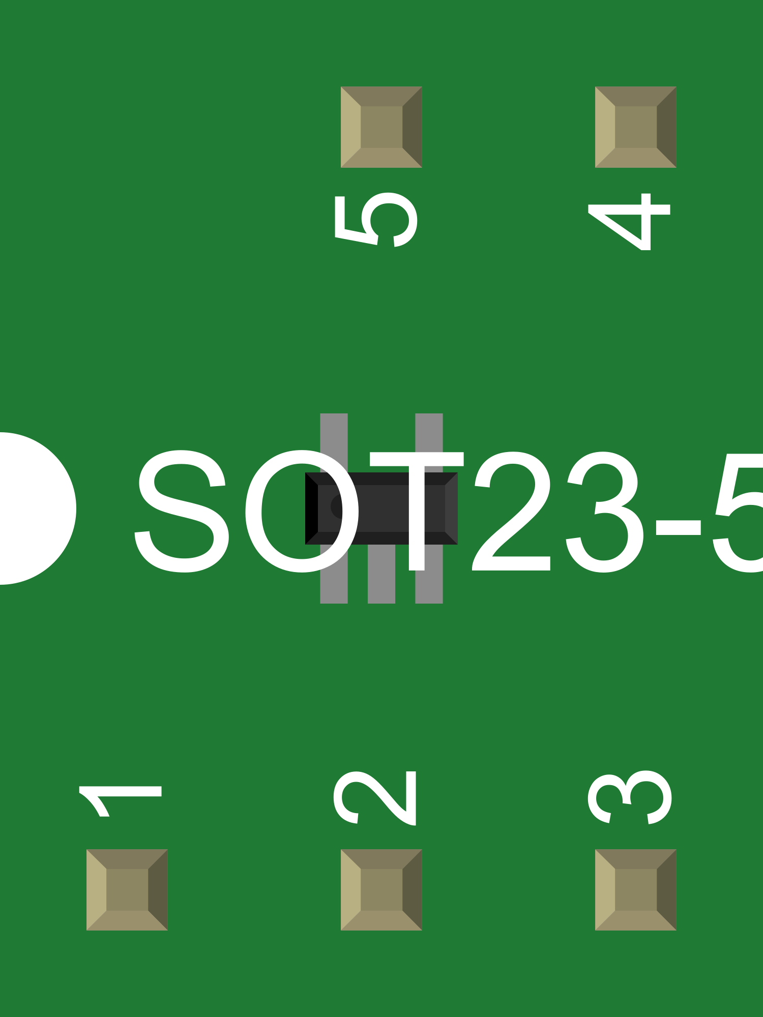
Pin Configuration and Descriptions
| Pin Number | Name | Description |
|---|---|---|
| 1 | Input | The input pin where the unregulated voltage is applied |
| 2 | Ground | The ground pin connected to the system ground |
| 3 | Output | The output pin providing the regulated voltage |
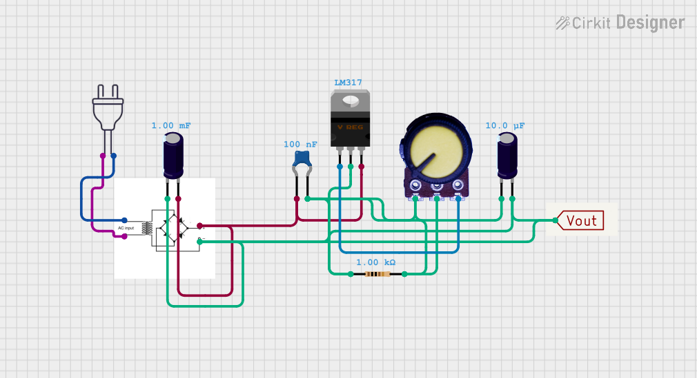
Usage Instructions
How to Use the Voltage Regulator in a Circuit
Connecting the Input: Connect the unregulated input voltage to the Input pin of the voltage regulator. Ensure that the voltage is within the specified input range.
Grounding: Connect the Ground pin to the common ground of your circuit.
Receiving the Output: Use the Output pin to connect to the circuit that requires regulated voltage.
Important Considerations and Best Practices
Heat Dissipation: Voltage regulators can generate significant heat during operation. It's important to consider heat sinking to dissipate excess heat and prevent overheating.
Capacitors for Stability: It is recommended to place a capacitor (typically 0.33uF) close to the input and a capacitor (typically 0.1uF) close to the output to improve stability and reduce noise.
Input Voltage: Ensure that the input voltage always exceeds the output voltage by at least the dropout voltage to maintain regulation.
Current Limiting: Be mindful of the maximum current rating. If your circuit draws more current than the regulator can handle, it may overheat or shut down.
Protection Diodes: In circuits where the output may be subjected to large transient voltages, protection diodes may be necessary to prevent damage to the regulator.
Troubleshooting and FAQs
Common Issues
Voltage Drop: If the output voltage is lower than expected, check that the input voltage is sufficient and that the regulator is not in thermal shutdown due to overheating.
Overheating: If the regulator is too hot to touch, ensure adequate heat sinking and verify that the current draw is within the specified limits.
Noise: If the output voltage is noisy, check the capacitors at the input and output for proper values and placement.
Solutions and Tips for Troubleshooting
Insufficient Output Voltage: Increase the input voltage or check for excessive load on the output.
Excessive Heat: Attach a heat sink to the regulator, reduce the load current, or improve airflow around the component.
Noise Issues: Ensure that the input and output capacitors are of the correct value and are located as close to the regulator as possible.
FAQs
Q: Can I use a voltage regulator to step up voltage? A: No, a typical linear voltage regulator like the LM7805 cannot step up voltage. It only steps down the voltage to a lower, regulated level.
Q: What happens if I exceed the maximum input voltage? A: Exceeding the maximum input voltage can damage the voltage regulator permanently.
Q: Can I connect multiple voltage regulators in parallel to increase current capacity? A: It is generally not recommended to connect linear regulators in parallel due to potential differences in output voltage and current sharing issues.
Example Connection with Arduino UNO
// No specific code is required for using a voltage regulator with an Arduino UNO.
// The regulator is used to provide a stable 5V to the Arduino's 5V pin if needed.

// However, here is a simple example of how to read the regulated 5V on an analog pin:

void setup() {
  Serial.begin(9600);
}

void loop() {
  int sensorValue = analogRead(A0); // Assuming the regulated 5V is connected to A0
  float voltage = sensorValue * (5.0 / 1023.0); // Convert the reading to voltage
  Serial.println(voltage);
  delay(1000); // Wait for a second before reading again
}

// Note: This code assumes that the Arduino is powered by another means and the
// voltage regulator's output is being measured. Do not connect the regulator's
// output directly to the 5V pin without disconnecting the Arduino from USB power.
Remember to follow the Arduino UNO's voltage input specifications when using an external voltage regulator.