How to Use 8-channel analog multiplexer/demultiplexer: Examples, Pinouts, and Specs
Introduction
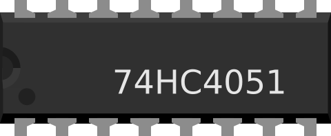
The 74HC4051 is an 8-channel analog multiplexer/demultiplexer manufactured by NXP Semiconductors. This versatile device allows the routing of one of eight input signals to a single output line or vice versa. It is commonly used in applications requiring signal selection, data acquisition, and analog signal routing.
Explore Projects Built with 8-channel analog multiplexer/demultiplexer


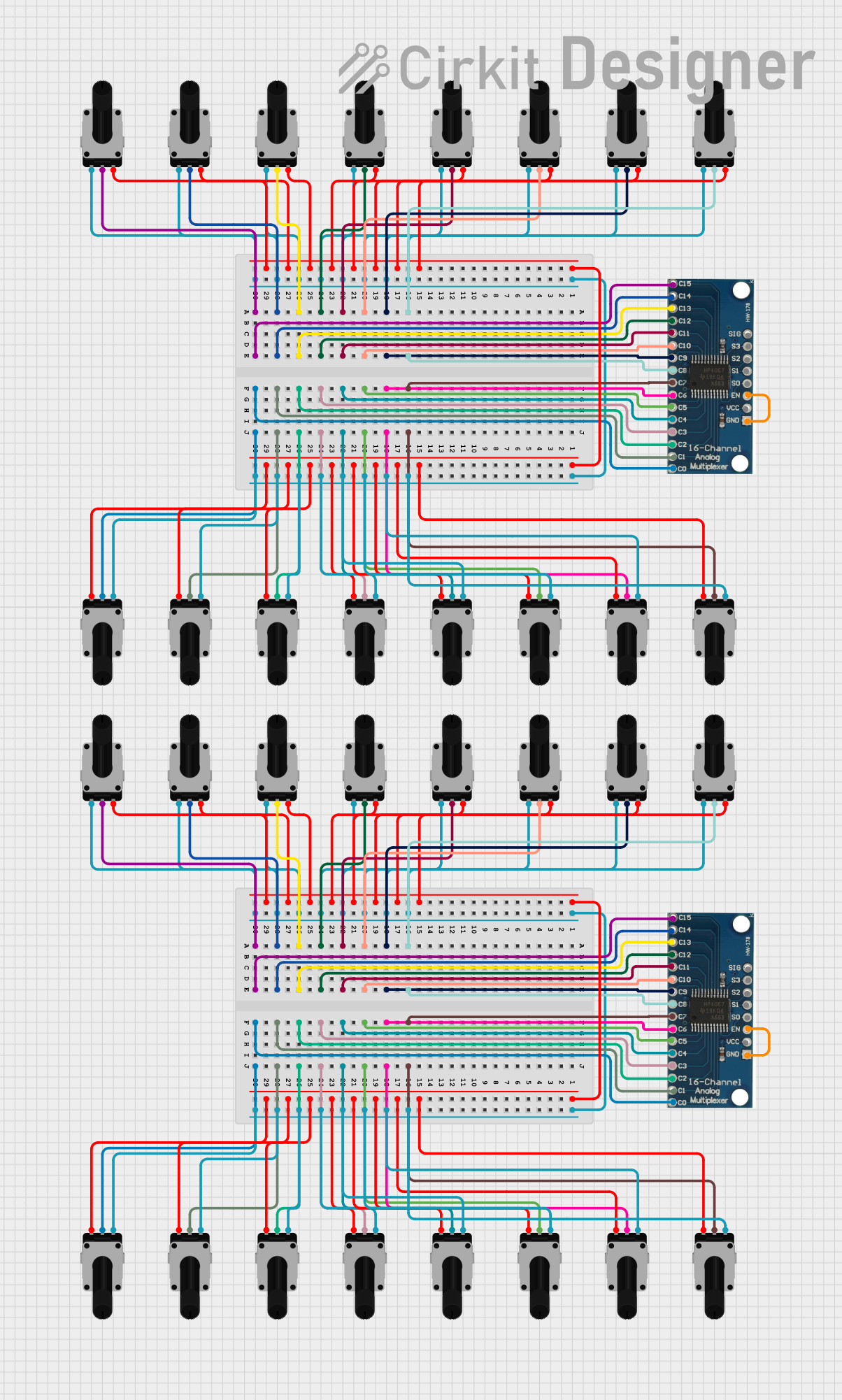

Explore Projects Built with 8-channel analog multiplexer/demultiplexer
Common Applications and Use Cases
- Analog signal selection in data acquisition systems
- Expanding the number of analog inputs for microcontrollers
- Audio signal routing and mixing
- Sensor multiplexing in embedded systems
- Test and measurement equipment
Technical Specifications
The 74HC4051 is a high-speed CMOS device that operates with both analog and digital signals. Below are its key technical details:
Key Technical Details
- Operating Voltage (Vcc): 2V to 10V
- Analog Signal Range: 0V to Vcc
- Control Logic Voltage Levels:
- Low: 0V to 30% of Vcc
- High: 70% of Vcc to Vcc
- On-Resistance (Ron): ~70Ω at Vcc = 5V
- Maximum Input Current: ±20mA
- Propagation Delay: ~10ns at Vcc = 5V
- Power Consumption: Low power CMOS technology
- Temperature Range: -40°C to +125°C
Pin Configuration and Descriptions
The 74HC4051 comes in a 16-pin package. Below is the pinout and description:
| Pin | Name | Description |
|---|---|---|
| 1 | S1 | Select line 1 (Control input) |
| 2 | S2 | Select line 2 (Control input) |
| 3 | S3 | Select line 3 (Control input) |
| 4 | Z | Common I/O (Analog signal input/output) |
| 5 | E | Enable pin (Active LOW, enables the multiplexer/demultiplexer) |
| 6-13 | Y0-Y7 | Analog channels (Y0 to Y7) |
| 14 | VEE | Negative supply voltage (typically connected to GND for single-supply operation) |
| 15 | VCC | Positive supply voltage |
| 16 | GND | Ground |
Usage Instructions
The 74HC4051 can be used to select one of eight analog signals or route a single signal to one of eight outputs. Below are the steps and considerations for using this component:
How to Use the Component in a Circuit
Power Supply:
- Connect the VCC pin to the positive supply voltage (e.g., 5V).
- Connect the GND pin to the ground.
- If using a single-supply configuration, connect VEE to GND. For dual-supply operation, connect VEE to a negative voltage (e.g., -5V).
Control Signals:
- Use the S1, S2, and S3 pins to select the desired channel (Y0-Y7). The binary combination of these pins determines the active channel.
- For example:
- S3, S2, S1 = 000 → Y0 is selected.
- S3, S2, S1 = 001 → Y1 is selected.
- S3, S2, S1 = 111 → Y7 is selected.
Enable Pin:
- The E pin must be set LOW to enable the device. If E is HIGH, all channels are disconnected.
Analog Signal Connection:
- Connect the analog signals to the Y0-Y7 pins.
- The selected signal will appear on the Z pin.
Important Considerations and Best Practices
- Ensure the analog signal voltage does not exceed the supply voltage range (0V to Vcc).
- Use pull-down resistors on the control pins to prevent floating inputs.
- Minimize the length of analog signal traces to reduce noise and signal degradation.
- For high-frequency signals, consider the on-resistance and capacitance of the device, as they may affect signal integrity.
Example: Connecting to an Arduino UNO
The 74HC4051 can be easily interfaced with an Arduino UNO to expand its analog input capabilities. Below is an example code snippet:
// Define control pins for the 74HC4051
const int S1 = 2;  // Select line 1
const int S2 = 3;  // Select line 2
const int S3 = 4;  // Select line 3
const int Z = A0;  // Common I/O connected to Arduino analog pin A0

void setup() {
  // Set control pins as outputs
  pinMode(S1, OUTPUT);
  pinMode(S2, OUTPUT);
  pinMode(S3, OUTPUT);

  // Initialize serial communication for debugging
  Serial.begin(9600);
}

void loop() {
  for (int channel = 0; channel < 8; channel++) {
    // Set the control pins to select the desired channel
    digitalWrite(S1, channel & 0x01);  // Least significant bit
    digitalWrite(S2, (channel >> 1) & 0x01);  // Second bit
    digitalWrite(S3, (channel >> 2) & 0x01);  // Most significant bit

    // Read the analog value from the selected channel
    int analogValue = analogRead(Z);

    // Print the channel and its value to the serial monitor
    Serial.print("Channel ");
    Serial.print(channel);
    Serial.print(": ");
    Serial.println(analogValue);

    delay(500);  // Wait for 500ms before reading the next channel
  }
}
Troubleshooting and FAQs
Common Issues and Solutions
No Signal on the Output (Z Pin):
- Ensure the E pin is set LOW to enable the device.
- Verify the control signals (S1, S2, S3) are correctly set for the desired channel.
Signal Distortion or Noise:
- Check that the analog signal voltage is within the specified range (0V to Vcc).
- Use decoupling capacitors near the power supply pins to reduce noise.
Incorrect Channel Selection:
- Verify the binary combination of the control signals matches the desired channel.
- Check for loose or incorrect connections on the control pins.
Device Overheating:
- Ensure the input current does not exceed the maximum rating of ±20mA.
- Avoid short circuits between the analog channels.
FAQs
Q1: Can the 74HC4051 handle digital signals?
Yes, the 74HC4051 can route both analog and digital signals, provided the signal levels are within the specified voltage range.
Q2: Can I use the 74HC4051 with a dual power supply?
Yes, the device supports dual-supply operation. Connect VEE to a negative voltage (e.g., -5V) for signals that swing below ground.
Q3: What is the maximum switching speed of the 74HC4051?
The propagation delay is approximately 10ns at Vcc = 5V, making it suitable for high-speed applications.
Q4: How do I prevent floating inputs on the control pins?
Use pull-down resistors (e.g., 10kΩ) on the control pins to ensure they are not left floating when not driven by a microcontroller.