How to Use analog joystick: Examples, Pinouts, and Specs
Introduction
An analog joystick is a control device that allows for two-dimensional input through the movement of a stick. It typically consists of a stick that pivots on a base and can detect the angle and direction of the movement. The joystick provides variable resistance and outputs analog signals corresponding to the X and Y axes. Many analog joysticks also include a push-button feature when the stick is pressed down.
Explore Projects Built with analog joystick


Explore Projects Built with analog joystick
Common Applications and Use Cases
- Gaming controllers for precise movement control
- Robotics for directional input
- Remote control systems for drones or vehicles
- User interface navigation in embedded systems
- Industrial control panels
Technical Specifications
Below are the key technical details of a standard analog joystick module:
| Parameter | Value |
|---|---|
| Operating Voltage | 3.3V - 5V |
| Output Type | Analog (X, Y axes) and Digital (button) |
| X-Axis Resistance Range | 0Ω to 10kΩ |
| Y-Axis Resistance Range | 0Ω to 10kΩ |
| Button Type | Momentary push-button |
| Dimensions | ~34mm x 34mm x 32mm |
Pin Configuration and Descriptions
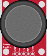
The analog joystick module typically has 5 pins. Below is the pinout:
| Pin | Name | Description |
|---|---|---|
| 1 | GND | Ground connection |
| 2 | +VCC | Power supply (3.3V or 5V) |
| 3 | VRx | Analog output for the X-axis (horizontal movement) |
| 4 | VRy | Analog output for the Y-axis (vertical movement) |
| 5 | SW | Digital output for the push-button (active LOW when pressed, HIGH otherwise) |
Usage Instructions
How to Use the Component in a Circuit
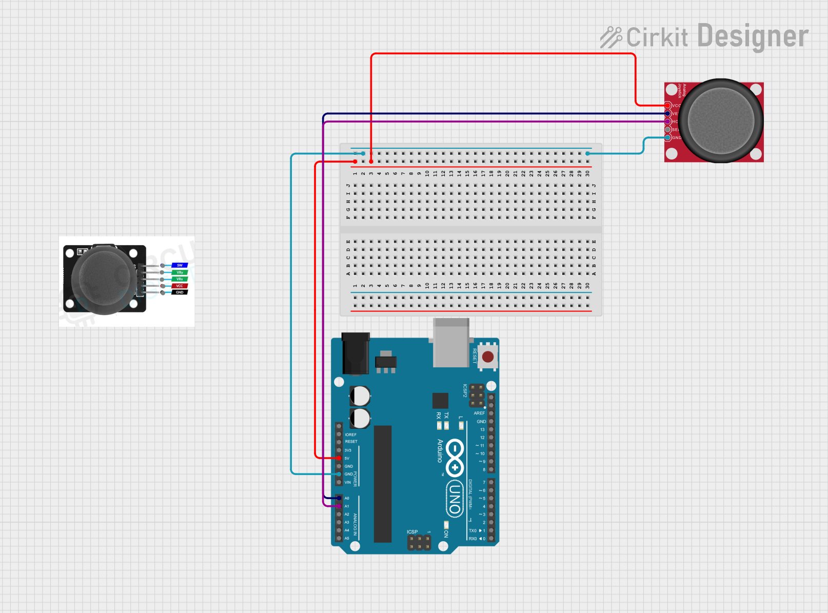
- Power the Joystick: Connect the
+VCCpin to a 3.3V or 5V power source and theGNDpin to ground. - Read the X and Y Axes: Connect the
VRxandVRypins to the analog input pins of a microcontroller (e.g., Arduino). These pins output a voltage proportional to the stick's position. - Read the Button State: Connect the
SWpin to a digital input pin of the microcontroller. Use a pull-up resistor if necessary, as the button output is active LOW.
Important Considerations and Best Practices
- Voltage Compatibility: Ensure the joystick's operating voltage matches your microcontroller's input voltage (3.3V or 5V).
- Debouncing the Button: If using the push-button, implement software debouncing to avoid false triggers.
- Calibration: The joystick's analog outputs may vary slightly due to manufacturing tolerances. Calibrate the X and Y axes in your software to ensure accurate readings.
- Mechanical Durability: Avoid applying excessive force to the joystick to prevent damage to the internal potentiometers.
Example Code for Arduino UNO
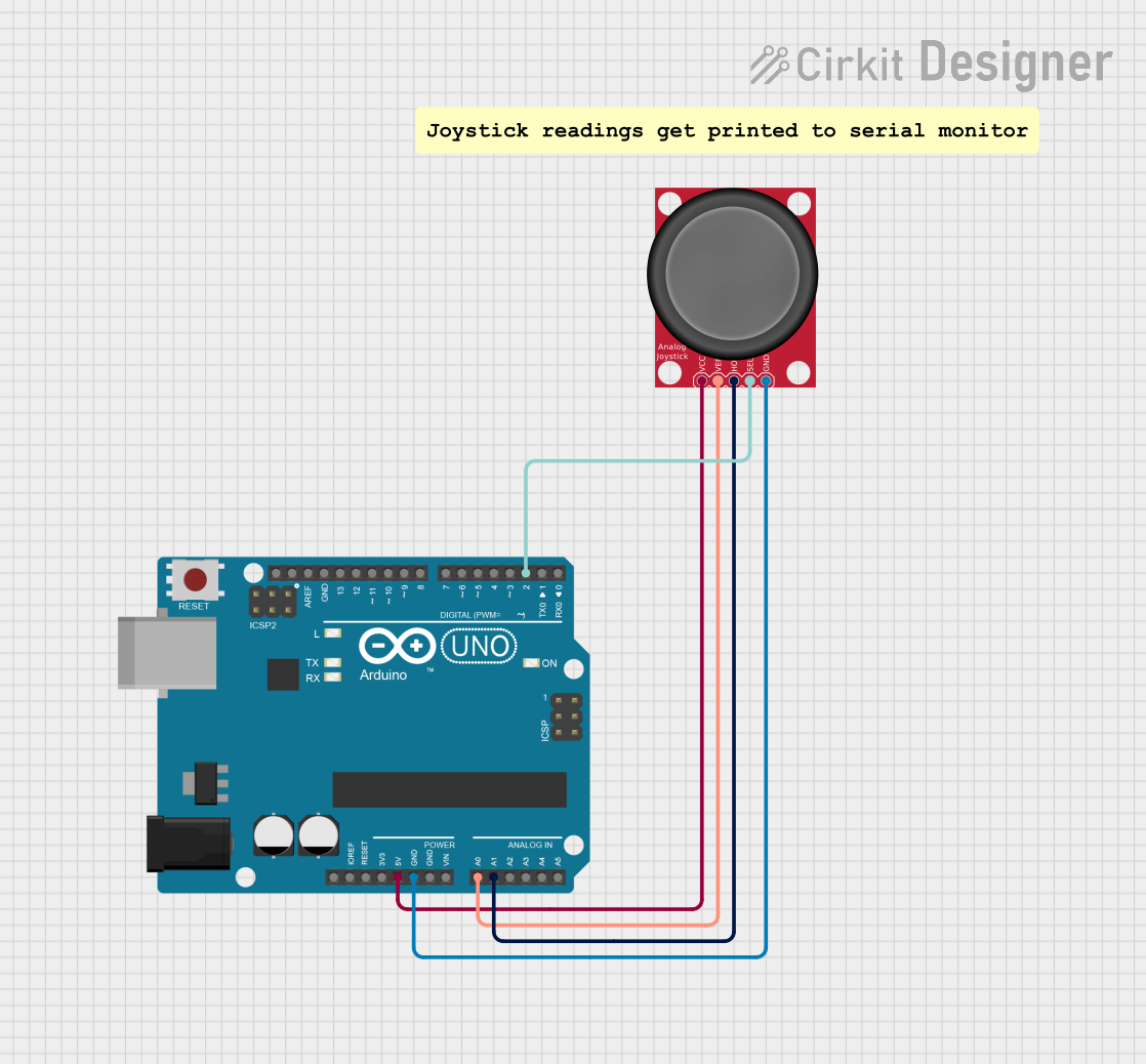
Below is an example of how to interface the analog joystick with an Arduino UNO:
// Define pin connections
const int VRxPin = A0; // X-axis connected to analog pin A0
const int VRyPin = A1; // Y-axis connected to analog pin A1
const int SWPin = 2;   // Push-button connected to digital pin 2

void setup() {
  // Initialize serial communication for debugging
  Serial.begin(9600);

  // Configure the button pin as input with internal pull-up resistor
  pinMode(SWPin, INPUT_PULLUP);
}

void loop() {
  // Read the X and Y axis values (0 to 1023)
  int xValue = analogRead(VRxPin);
  int yValue = analogRead(VRyPin);

  // Read the button state (LOW when pressed, HIGH otherwise)
  int buttonState = digitalRead(SWPin);

  // Print the values to the Serial Monitor
  Serial.print("X: ");
  Serial.print(xValue);
  Serial.print(" | Y: ");
  Serial.print(yValue);
  Serial.print(" | Button: ");
  Serial.println(buttonState == LOW ? "Pressed" : "Released");

  // Add a small delay for stability
  delay(100);
}
Troubleshooting and FAQs
Common Issues and Solutions
No Output from X or Y Axis
- Cause: Loose or incorrect wiring.
- Solution: Verify that the
VRxandVRypins are properly connected to the microcontroller's analog input pins.
Button Not Responding
- Cause: Missing pull-up resistor or incorrect pin configuration.
- Solution: Use the
INPUT_PULLUPmode in your code or add an external pull-up resistor to theSWpin.
Inconsistent or Noisy Readings
- Cause: Electrical noise or poor power supply.
- Solution: Add decoupling capacitors (e.g., 0.1µF) between
+VCCandGNDnear the joystick module.
Joystick Center Position Not Reading 512
- Cause: Manufacturing tolerances or wear over time.
- Solution: Implement software calibration to adjust the center position.
FAQs
Q: Can I use the joystick with a Raspberry Pi?
A: Yes, the joystick can be used with a Raspberry Pi. Connect the analog outputs (VRx and VRy) to an ADC (Analog-to-Digital Converter) module, as the Raspberry Pi does not have built-in analog input pins.
Q: What is the lifespan of an analog joystick?
A: The lifespan depends on the quality of the joystick and usage conditions. Most joysticks are rated for tens of thousands of movements.
Q: Can I use the joystick for 3D input?
A: No, standard analog joysticks only provide 2D input (X and Y axes). For 3D input, specialized joysticks or sensors are required.