
How to Use I2C Non-Volatile FRAM 32KB: Examples, Pinouts, and Specs
 Design with I2C Non-Volatile FRAM 32KB in Cirkit Designer
Introduction
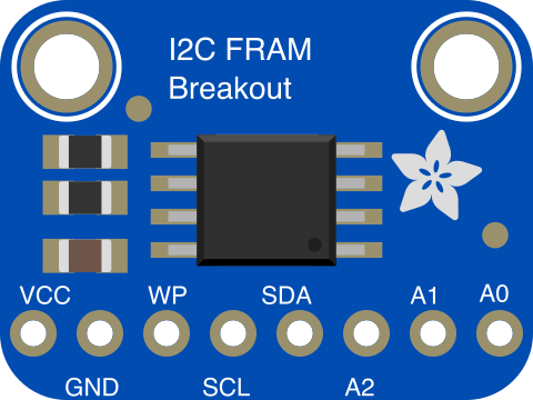
The Adafruit I2C Non-Volatile FRAM 32KB (Part ID: 1895) is a high-performance memory component that provides 32 kilobytes of non-volatile storage. Unlike traditional EEPROMs, this FRAM (Ferroelectric Random Access Memory) offers faster write speeds, higher endurance, and lower power consumption. It communicates via the I2C interface, making it easy to integrate into microcontroller-based projects.
Explore Projects Built with I2C Non-Volatile FRAM 32KB
 Open Project in Cirkit Designer
 Open Project in Cirkit Designer
 Open Project in Cirkit Designer
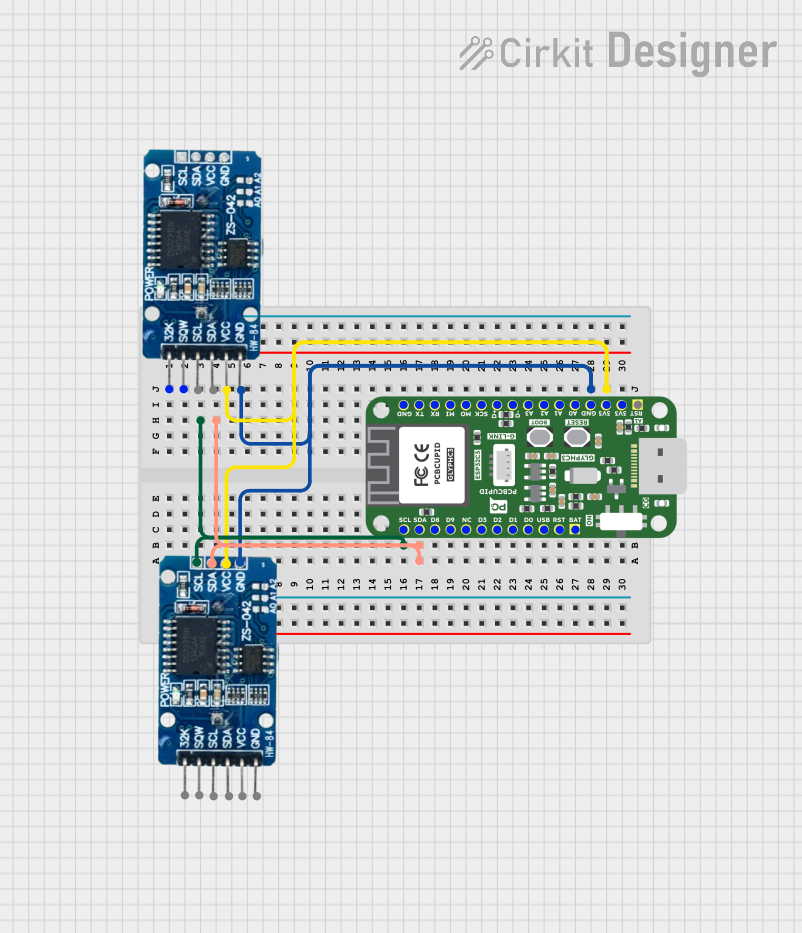 Open Project in Cirkit Designer
Explore Projects Built with I2C Non-Volatile FRAM 32KB
Open Project in Cirkit DesignerOpen Project in Cirkit DesignerOpen Project in Cirkit DesignerOpen Project in Cirkit DesignerCommon Applications and Use Cases
- Data logging and storage in IoT devices
- Storing configuration settings or calibration data
- Applications requiring frequent write cycles (e.g., sensor data storage)
- Power-failure-resistant memory for critical systems
Technical Specifications
The following table outlines the key technical details of the Adafruit I2C Non-Volatile FRAM 32KB:
| Parameter | Value |
|---|---|
| Memory Size | 32 KB (256 Kbits) |
| Interface | I2C (Inter-Integrated Circuit) |
| Operating Voltage | 2.7V to 5.5V |
| Write/Read Speed | Up to 1 MHz (I2C clock speed) |
| Endurance | 10 trillion (10^13) write cycles |
| Data Retention | 95 years at 85°C |
| Operating Temperature | -40°C to +85°C |
| Dimensions | 25mm x 17mm x 2mm (PCB size) |
Pin Configuration and Descriptions
The Adafruit I2C Non-Volatile FRAM 32KB module has the following pinout:
| Pin | Name | Description |
|---|---|---|
| 1 | VIN | Power input (2.7V to 5.5V). Connect to the power supply of your microcontroller. |
| 2 | GND | Ground. Connect to the ground of your circuit. |
| 3 | SCL | I2C clock line. Connect to the SCL pin of your microcontroller. |
| 4 | SDA | I2C data line. Connect to the SDA pin of your microcontroller. |
| 5 | WP | Write Protect. Pull high to disable writes; pull low to enable writes. |
Usage Instructions
How to Use the Component in a Circuit
- Power the Module: Connect the
VINpin to a 3.3V or 5V power source and theGNDpin to ground. - Connect I2C Lines: Attach the
SCLandSDApins to the corresponding I2C pins on your microcontroller. - Optional Write Protection: If you want to prevent accidental writes, pull the
WPpin high. Leave it low or unconnected for normal operation. - Pull-Up Resistors: Ensure that your I2C bus has pull-up resistors (typically 4.7kΩ) on the
SCLandSDAlines. Some microcontroller boards, like the Arduino UNO, already include these resistors.
Important Considerations and Best Practices
- I2C Address: The default I2C address for this module is
0x50. Ensure no other devices on the I2C bus share this address. - Write Protection: Use the
WPpin to safeguard critical data from being overwritten. - Power Supply: Ensure a stable power supply to avoid data corruption during read/write operations.
- Data Retention: While the FRAM is non-volatile, avoid exceeding the endurance limit of 10 trillion write cycles for any single memory location.
Example Code for Arduino UNO
Below is an example of how to use the Adafruit I2C Non-Volatile FRAM 32KB with an Arduino UNO. This code writes a string to the FRAM and then reads it back.
#include <Wire.h>
#include "Adafruit_FRAM_I2C.h"

// Create an FRAM object
Adafruit_FRAM_I2C fram = Adafruit_FRAM_I2C();

// Variable to store the FRAM address
uint16_t framAddr = 0;

void setup() {
  Serial.begin(9600);
  while (!Serial) {
    delay(10); // Wait for Serial Monitor to open
  }

  // Initialize the FRAM module
  if (!fram.begin(0x50)) { // Default I2C address is 0x50
    Serial.println("Could not find FRAM. Check wiring!");
    while (1);
  }
  Serial.println("FRAM initialized!");

  // Write data to FRAM
  framAddr = 0; // Start at address 0
  const char *data = "Hello, FRAM!";
  for (uint8_t i = 0; i < strlen(data); i++) {
    fram.write8(framAddr++, data[i]);
  }
  Serial.println("Data written to FRAM.");
}

void loop() {
  // Read data back from FRAM
  framAddr = 0; // Start at address 0
  Serial.print("Data read from FRAM: ");
  while (framAddr < 12) { // Read 12 bytes (length of "Hello, FRAM!")
    char c = fram.read8(framAddr++);
    Serial.print(c);
  }
  Serial.println();

  delay(5000); // Wait 5 seconds before repeating
}
Code Explanation
- The
Adafruit_FRAM_I2Clibrary is used to interface with the FRAM module. - The
fram.write8()function writes a single byte to a specified memory address. - The
fram.read8()function reads a single byte from a specified memory address. - The example writes the string "Hello, FRAM!" to the FRAM and then reads it back.
Troubleshooting and FAQs
Common Issues and Solutions
FRAM Not Detected
- Cause: Incorrect wiring or I2C address conflict.
- Solution: Verify the connections to the
SCLandSDApins. Ensure no other devices on the I2C bus share the same address (0x50).
Data Corruption
- Cause: Unstable power supply or exceeding write endurance.
- Solution: Use a stable power source and avoid excessive writes to the same memory location.
Write Protection Not Working
- Cause:
WPpin not properly configured. - Solution: Ensure the
WPpin is pulled high to enable write protection.
- Cause:
FAQs
Q: Can I change the I2C address of the FRAM module?
A: No, the I2C address (0x50) is fixed and cannot be changed.
Q: Do I need external pull-up resistors for the I2C lines?
A: Many microcontroller boards, like the Arduino UNO, include built-in pull-up resistors. If your board does not, you will need to add 4.7kΩ resistors to the SCL and SDA lines.
Q: How long does the data remain stored in the FRAM?
A: The data retention is rated for 95 years at 85°C, making it highly reliable for long-term storage.
Q: Can I use this module with a 3.3V microcontroller?
A: Yes, the module supports operating voltages from 2.7V to 5.5V, making it compatible with both 3.3V and 5V systems.